Okay, so what hare the magic values?Here is a low cost oscillation sniffer. You can build it into an old marker pen case. It usefully covers c. 100KHz to a few MHz - just where there are usually problems in audio.
")
R1 - 47K ohm
R2 - 1k ohm
R3 - 47K ohm
C1 - 100pf
C2 - 1uf
D1 - 1N4148
So, did we get that right?
You need to be sure the 4558 is audio related in its use. It seems odd to use a mediocre opamp along with 5532's.
Hi Mooly
Would a CD player just have one 5532 and no other opamp in the audio section. I messed up the 4558, they still make them i thinnk
Okay, so what hare the magic values?
R1 - 47K ohm
R2 - 1k ohm
R3 - 47K ohm
C1 - 100pf
C2 - 1uf
D1 - 1N4148
So, did we get that right?
By the way, suggest that you insert a 10 nF capacitor between the input and the 1 k resistor - this will ensure the sniffer does not interfere with any DC biasing or DC loading.
I will go out on a limb and say that op amp swapping is not exactly rocket science, and can be done very effectively if one just observes the precautions outlined here earlier. The things that MUST be done, IMO, are:
- Use machined IC sockets (MillMax 110-47-308-41-001000)
- Put a 100nF X7R capacitor between the + and - power supply rails. A Vishay A104M15X7RF5TAA works nicely and fits easily between pins 4 and 8 of the MillMax DIP-8 socket
- Put a 22pF COG (NPO) capacitor in parallel with any negative feedback resistors in your circuits. (Murata RCE5C1H220J0A2H03B)
- This will limit the bandwidth sufficiently to avoid oscillation problems and still not affect performance in audio circuits.
Last edited:
My experience is machined IC sockets tend to end up in bent pins, whereas the standard flat spring variety are generally reliable and cheaper. I know they have fewer nominal insertion cycles in the datasheet, but they are less likely to lead (sic) to damaged ICs, and much less fussy about lead dressing and alignment during insertion. Besides 50 insertion cycles is probably enough - if you want more than this surely a ZIF socket is more what's needed?
That may be your experience, and I do suppose it matters greatly WHICH "standard flat spring variety" of IC socket you use. But I spent about three weeks changing out every flat spring socket in a well-known (and expensive) video processor because they were so unreliable---we literally had to "exercise" all eighty boards in that device every morning to try to get through the day's sessions. I have NEVER seen a MillMax gold plated socket have ANY such problems.
If I may - for anyone with any interest in hands-on electronics an oscilloscope is a lot like, say, an air compressor or a Workmate: once you have one, you will not understand how you ever went through life without one.I don't like being brow-beaten (esp. by a moderator!) into spending $150-200 minimum on a tool that might get used once a year. Seriously. Is that unreasonable?
(One of NP's early articles, A40, even has a suggestion on how to check DC at the outputs for the DIYer who HAS NO volt meter....!)
Excellent description,Think of the scope input as like an input on an amplifier. It has an outer ground and an inner signal.
Probes come in all shapes and sizes and complexity right down to just a wire with croc clips
For initial experimenting (if you can't find a probe) is just two lengths of wire. The ground of the audio out on the player goes to the ground on the scope. There will probably be a big ground terminal (screw/nut) right on the front which you can use. The other wire just goes in the centre of the "BNC" type connector on the scopes "Y" input and to the centre of the RCA output on the player.
That will get you started. If you have a probe then you can start looking at the opamp outputs directly.
Great to read through the older posts
I have three scopes and two spectrum analyzers. More than I need, but not as many as I want. A scope to an EE is like a hammer to a roofer. If you can fly a wideband analog scope well, you can see just about everything you need to see. (Except RF>400MHz and audio distortion <.5%).
Sorry to dig up this old post. But I am reading up on how to resolve my osilation problems.The subject of swapping op-amps is one of the more frequent topics to crop up on these forums... and regulars will know that I often add a proviso that you should ALWAYS check that the replacement is at the very least stable. Never assume it will be.
So here just to show what I mean is a simple op-amp swap of the sort that crops up on diyAudio all the time.
The circuit shown was designed for the NE5534 with no external compensation used on the op-amp. A typical scenario then, where everyone has their own ideas and favourites on what to fit. What could possibly go wrong... a double sided PCB with large ground planes with extensive decoupling and local regulators it is a model of impeccable layout.
The opamp we are replacing is U30 that sums the output of the DAC. The two scope traces show the substituted op-amp as the top trace and the original as the lower trace. The scope was on the output of U30
The first picture is of the OPA604 FET opamp, one of my personal favourites. Straight away it is obvious that something is not right... the trace is "thicker", a classic effect of very high frequency instability. This was playing a 1khz track at around -40 db. The frequency of oscillation was around 1.8 Mhz and around 0.6 volts peak to peak.
Second shot is the AD797 op-amp. Here the track played is 1 khz at 0db. As can be seen the op-amp is oscillating like crazy. To see just how crazy look at the next shot.
Third shot is the player in stop mode leaving just the oscillation. It's around 1.4Mhz but at a whopping 6 volts peak to peak.
Fourth shot is the output of the op-amp with a 5pf cap across R33... clean with just a small amount of HF hash from the DAC itself that the following stage (the low pass filter) removes.
Would you know it was unstable by listening ? Well actually, you may not, and may put the change in sound down to the op-amp ! The AD797 certainly sounded over bright and thin but I can imagine some saying, "hey listen to that extra detail" it just shows how murky and dull the 5534 was. A bit extreme maybe, but you see my point.
The OPA604... far more subtle and many wouldn't notice the problem in a lot of systems.
So I hope that helps explain the "always check for stabilty etc" that I always trot out, and some of you reading this are probably doing so because I just linked your thread on "what should I replace xxxxxx with" to this one
Happy swapping...
Just some observations.
1. Some people swear that the sound is improved. With the oscillations. In double blind tests they pick the board with osilations every single time. My OCD doesn't care about the sound I just want a clean signal. I even had a friend tell me that the osilations are part of the magic. lol
2. If you remember my post I had one board which worked clean and all the others had the osilations. So I opted to make the clean board my test jig.
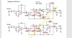
And to test the op amps from the boards that were oscillating. Guess what I found. ?. All my op amps were clean in the test jig. So then I started to look at the components. And the board that worked had this 30 Pf cap between pins 6 and 7 and 2 and 1.
But in your post you say you cured it by putting a 5pf between R33 so basically your saying pins 2 and 6.
This has confused me.
Please find attached the circuit of the board which works for me. The stuff marked in red are changes I found on my board. My board also uses the NE chip not the 4558.
This board works with zero oscillations the only problem is the Mids control is not so good need to work on that.
Attachments
I got this board with NE 5532 op amps.Let's get some things straight here - is the circuit oscillating with the original 4558 parts, or did you swap in something else that caused the problem? Do tell... It's quite an accomplishment getting the 4558s to oscillate, as they are on the slow side.
I asked the guy who sold me the board to share the schematic with me.
This is the schematic he sent me. What changes I found on the board I marked in red.
- Home
- Source & Line
- Analog Line Level
- Swapping Op-Amps... you have checked to see it's stable haven't you ?