Volume & selector controller with 5x7 dotmatrix display for tube/transistor amplifier
Hi,
It is my first post on this forum.
I would like to present my latest project:
Volume & selector controller with dot matrix display for tube amplifiers.
The controller is designed to:
- volume control in audio systems by motorized potentiometer
- relay input selector control (4 inputs)
- switching cycle control for tube amplifiers (relays for V_heater, V_anode, Speakers)
- additional relay output control
- measurement of amplifier’s tubes working time
Main features:
- IR remote (RC5,SONY and NEC IR transmission standards)
- motorized potentiometer controlled by IR remote, keyboard or encoder (2 types)
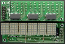
- LED dot matrix display (6 characters, 5x7 dots, 0.7 inches)
- dimmer with 3 programmable levels
- automatic blanking
- input selector (max 4 inputs)
- selector controlled by IR remote, keyboard or encoder (2 types)
- sleep timer (1-99min)
- programable switching cycle control for tube amplifiers
- automatic switching off V_anode in mute state
- individual timers (working time) for 6 tubes
- all displayed messages programmable by user
- configuration made by keyboard (configuration menu) or RS232 port (terminal)
- firmware upgradable by RS232 port (without any additional hardware)
The controller can be fully configured by user.
The main parameters are:
- IR remote standard
- IR remote address
- IR remote scan codes (Volume+-, Selector+-, Mute, Dimmer, Timer, Menu ...)
- IR remote key repetition parameters
- volume control type (IR, keyboard, encoder)
- number of selector inputs
- control type selector (IR, keyboard, encoder)
- names of inputs
- pulse duration of motor control
- dimmer levels
- display blanking time
- times between activation of V_heater,V_anode, Speakers
- names of tubes
- ...
There are about fifty differrend parameters.
I have full user manual written in polish so I must translate it to english.
But my english is bad so, it is difficult for me.
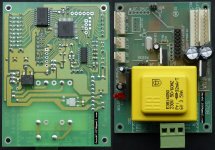
Today schematics and some photos.
Best Regards
JarekC
Hi,
It is my first post on this forum.
I would like to present my latest project:
Volume & selector controller with dot matrix display for tube amplifiers.
The controller is designed to:
- volume control in audio systems by motorized potentiometer
- relay input selector control (4 inputs)
- switching cycle control for tube amplifiers (relays for V_heater, V_anode, Speakers)
- additional relay output control
- measurement of amplifier’s tubes working time
Main features:
- IR remote (RC5,SONY and NEC IR transmission standards)
- motorized potentiometer controlled by IR remote, keyboard or encoder (2 types)
- LED dot matrix display (6 characters, 5x7 dots, 0.7 inches)
- dimmer with 3 programmable levels
- automatic blanking
- input selector (max 4 inputs)
- selector controlled by IR remote, keyboard or encoder (2 types)
- sleep timer (1-99min)
- programable switching cycle control for tube amplifiers
- automatic switching off V_anode in mute state
- individual timers (working time) for 6 tubes
- all displayed messages programmable by user
- configuration made by keyboard (configuration menu) or RS232 port (terminal)
- firmware upgradable by RS232 port (without any additional hardware)
The controller can be fully configured by user.
The main parameters are:
- IR remote standard
- IR remote address
- IR remote scan codes (Volume+-, Selector+-, Mute, Dimmer, Timer, Menu ...)
- IR remote key repetition parameters
- volume control type (IR, keyboard, encoder)
- number of selector inputs
- control type selector (IR, keyboard, encoder)
- names of inputs
- pulse duration of motor control
- dimmer levels
- display blanking time
- times between activation of V_heater,V_anode, Speakers
- names of tubes
- ...
There are about fifty differrend parameters.
I have full user manual written in polish so I must translate it to english.
But my english is bad so, it is difficult for me.
Today schematics and some photos.
Best Regards
JarekC
Attachments

") I've been meaning to get to work on something like this forever but never got to. This will make for a very start
I've been meaning to get to work on something like this forever but never got to. This will make for a very start Information Continued:
Below nemes and descriptions of all programed parameters:
Name: Descriptions:
IR = IR remote type 0=RC5 1=NEC 2=SONY
AD = IR remote address 0-255
PO = IR remote scan code Power On/Off
V+ = IR remote scan code Volume+
V- = IR remote scan code Volume-
MU = IR remote scan code Mute
S+ = IR remote scan code Selector+
S- = IR remote scan code Selector-
S1 = IR remote scan code Selector In1
S2 = IR remote scan code Selector In2
S3 = IR remote scan code Selector In3
S4 = IR remote scan code Selector In4
OT = IR remote scan code Out Relay4 *
DI = IR remote scan code Dimmer *
TI = IR remote scan code Sleep timer *
TU = IR remote scan code Tube timers *
CL = IR remote scan code Clock *
ME = IR remote scan code Menu
* if scancode is the same as ME (Menu scan code) this fuction will be
supported by menu
REP = Type of key repetition 0=IR remote 1=delayed 2=dynamic
RST = Repetition start delay 0-30 (only if deleayed or dynamic)
RSL = Slow repetition 0-30 (only if dynamic)
VCTL= Volume control 0=IR 1=IR&Keys+- 2=IR&Encoder type1 3=IR&Encoder type
M1 = First motor impulse 5-250ms
M2 = Next motor impulse 5-250ms
SCTL = Selector control 0=IR&Keys1234 1=IR&Keys+- 2=IR&Encoder type1 3=IR&Encoder type2
SMAX = Number of selector inputs 1-4
MCTL = Mute control 0=by Selector 1=by Speaker relay
T1 = Time between switching on Relay1(V_heater) -> Relay2(V_anode) 0-99sec.
T2 = Time between switching on Relay2(V_anode) -> Relay3(Speakers) 0-99sec.
T3 = Time between switching off Relay3(Speakers) -> Relay2(V_anode) 0-99sec.
T3 = Time between switching off Relay2(V_anode) -> Relay1(V_heater) 0-99sec.
TM = Time bettween Mute On and switching off Realy2(V_anode) 0-240 unit 15s -> 15s-1h 0=not used
D1 = Dimmer level 1 0-29
D2 = Dimmer level 2 0-29
D3 = Dimmer level 3 0-29
DC = Dimmer level for clock 0-29
TB = Display blanking time 0-240 unit 5s -> 5s-20min 0=not used
TCNT1 = Tube 1 timer (read only or reset)
TCNT2 = Tube 2 timer (read only or reset)
TCNT3 = Tube 3 timer (read only or reset)
TCNT4 = Tube 4 timer (read only or reset)
TCNT5 = Tube 5 timer (read only or reset)
TCNT6 = Tube 6 timer (read only or reset)
String definition.
ASCII chars range 32-127,171-arrow down, 187-arrow up
For SON1,SON2,SOFF1,SOFF2 putting -- on two last positions will display timer.
SIN1 = Input 1 name
SIN2 = Input 2 name
SIN3 = Input 3 name
SIN4 = Input 4 name
SMUTE = Mute
SVOL+ = Volume up
SVOL- = Volume down
SON1 = On Rel1->Rel2 (V_heater->V_anode)
SON2 = On Rel2->Rel3 (V_anode->Speakers)
SOFF3 = Off Rel3->Rel2 (Speakers->V_anode)
SOFF4 = Off Rel2->Rel1 (V_anode->V_heater)
SOON = On Realy4
SOOFF = 0ff Realy4
SDIMM = Dimmer
STUBE = Tube timers
STOT = Controller timer
ST1 = Tube 1 name
ST2 = Tube 2 name
ST3 = Tube 3 name
ST4 = Tube 4 name
ST5 = Tube 5 name
ST6 = Tube 6 name
Best Regards
JarekC
Hi,
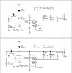
I made a few improvements in firmware and now it is possible to display the current time (in StanBy mode). Time display brightness is controlled by the parameter DC.
Real Time Clock is based on PCF8563 or PCF8583 chips.
RTC is connectet to J5.
Below schematic of required RTC circuit.
I also working on a version for PGA2310/2311 chips (in place of amotorized potentiometr)
Best regards
JarekC
Attachments
- Status
- This old topic is closed. If you want to reopen this topic, contact a moderator using the "Report Post" button.