Hi all,
I just want input for this Xiang Sheng 728A I want to mods it
This amp using 12AT7×2pcs, 12AU7×2pcs, 6Z4×2pcs
My questions should I change
I just want input for this Xiang Sheng 728A I want to mods it
This amp using 12AT7×2pcs, 12AU7×2pcs, 6Z4×2pcs
My questions should I change
- Tube to brand telfunken / mullard or any suggestions
- Upgrading Capacitor? Which one I should upgrade
Attachments
Hi Tony,
This unit is very very popular in China. It sells around 15 units a month. However, it seems that it hasn't really made its way among foreigners.
I just ordered mine yesterday and I am going to HK to pick it up next week.
Did you find any info with regards to mods? By speaking with the factory I understand that they have already improved a lot of the weak components from the 1 st version (the one from 2006) in the new model (including the tubes from 6N1 to 12AT7).
The lady from the factory said that their clients are actually quite happy with the stock tubes.
FYI, these are a few of the tubes that the unit can cope with (according to them):
12AT7 can be replaced with ECC81, 6201, 12AT7GT, etc.
12AU7 can be replaced with ECC82, 6N10, 6189, 12AU7GT, etc.
Did you try any other tube? Any mods?
Happy with the unit?
Thanks,
Serge
I stumbled upon this unit. I am trying to not buy it! Here is a good review but in Spanish. Perhaps Google translate will help. Also in that thread, is a link to a really thorough upgrade of a similar unit...
Análisis de un amplificador chino
Análisis de un amplificador chino
PARAGON AUDIO (FRANCIS JANSZ)
I have bought the XIANG SHENG DAC CONVERTER, And was very happy with it and Compared it with THE BRITISH MADE MUSICAL FIDELITY and THE MAKINGSTOCH DAC, I believe that it sounded a little better in the MIDRANGE And lacked a little in The Bottom end, But Value for money ALL in ALL it is Well Built and Very Pleasent on Hearing test We had 10 Listerners all blind folded, when conducting the listening test, 6 out of 10 Prefered THE DAC From XIANG SHENG, 4 out of Ten commented that it was lacking a bit on the Bottom End, 7 out of Ten Loved The High's
, and after running several test , 7 out of 10 Stated that they will Buy The Same DAC Converter. 3 out of 10 Immediately placed orders From MR: YOUNG LEE. and 3 Out of 10 Also placed orders FOR THE DAC and The 728 A Pre AMP That Includes. me, as I just placed my order on the 5/10/16, and should get delivery in around 10 working days. Once I get my unit I will first try it for a few months before Replacing The Better Tubes and Changing The Caps to Same Value Caps with AUDYN CAPS, and also Change The OUTPUT Wires With SOLID CORE TREATED WIRES. as advised by my Technician, I believe this will make this unit sound great and could be rated with Pre Amps that Cost around $:3,500 to around $4,500, And all in all This Pre AMP can be bought for about $375 USD and The upGrade could Cost Around $ 230, USD Total Cost for a Good Sounding PRE AMP will be around $ 605 USD, in comparission to Spending $ around $:4,000,
I personelly will be Happy to spend $:605 instead of Spending $4,000 To Get The same Results.
I think that This Pre amp is a Very good buy.
Kind Rgds
Francis Jansz
Dear SERGE,Hi Tony,
This unit is very very popular in China. It sells around 15 units a month. However, it seems that it hasn't really made its way among foreigners.
I just ordered mine yesterday and I am going to HK to pick it up next week.
Did you find any info with regards to mods? By speaking with the factory I understand that they have already improved a lot of the weak components from the 1 st version (the one from 2006) in the new model (including the tubes from 6N1 to 12AT7).
The lady from the factory said that their clients are actually quite happy with the stock tubes.
FYI, these are a few of the tubes that the unit can cope with (according to them):
12AT7 can be replaced with ECC81, 6201, 12AT7GT, etc.
12AU7 can be replaced with ECC82, 6N10, 6189, 12AU7GT, etc.
Did you try any other tube? Any mods?
Happy with the unit?
Thanks,
Serge
I have bought the XIANG SHENG DAC CONVERTER, And was very happy with it and Compared it with THE BRITISH MADE MUSICAL FIDELITY and THE MAKINGSTOCH DAC, I believe that it sounded a little better in the MIDRANGE And lacked a little in The Bottom end, But Value for money ALL in ALL it is Well Built and Very Pleasent on Hearing test We had 10 Listerners all blind folded, when conducting the listening test, 6 out of 10 Prefered THE DAC From XIANG SHENG, 4 out of Ten commented that it was lacking a bit on the Bottom End, 7 out of Ten Loved The High's
, and after running several test , 7 out of 10 Stated that they will Buy The Same DAC Converter. 3 out of 10 Immediately placed orders From MR: YOUNG LEE. and 3 Out of 10 Also placed orders FOR THE DAC and The 728 A Pre AMP That Includes. me, as I just placed my order on the 5/10/16, and should get delivery in around 10 working days. Once I get my unit I will first try it for a few months before Replacing The Better Tubes and Changing The Caps to Same Value Caps with AUDYN CAPS, and also Change The OUTPUT Wires With SOLID CORE TREATED WIRES. as advised by my Technician, I believe this will make this unit sound great and could be rated with Pre Amps that Cost around $:3,500 to around $4,500, And all in all This Pre AMP can be bought for about $375 USD and The upGrade could Cost Around $ 230, USD Total Cost for a Good Sounding PRE AMP will be around $ 605 USD, in comparission to Spending $ around $:4,000,
I personelly will be Happy to spend $:605 instead of Spending $4,000 To Get The same Results.
I think that This Pre amp is a Very good buy.
Kind Rgds
Francis Jansz
I Just Got Delivery of My XIANG SHENG 728 A PRE AMP. I have just opened the Box and Noticed That There are 2 OUTPUT LINES ON The BACK PANEL 1 HIGH OUTPUT and 1 LOW Output, THE ADMIN OFFICER has Advised me That I Can Connect The HIGH FULL SPECTRUM Iine Out to My LUXMAN A 2003 3 WAY all TUBE ACTIVE CROSSOVER INPUT.
AND I can Also Connect The PRE AMP LOW OUTPUT Line To My POWERED SUBWOOFER and Both Outputs WILL Work Safely without any Signal Loss.
I was also Told That This PRE amp is Not in CLASS A Operation, Now I would like to know if There is ANY MODIFICATIONS THAT CAN BE DONE TO RUN IT IN CLASS A OPERATION. if So I would like to know what alterations i will have to do by a quallified technician.
This Will help me to get the results i need .
Kind Rgds
Francis Jansz
Dear Friend,
I took your ADVISE and Bought the XIANG SHENG 728 A Pre AMP, My Technician Checked it out and Stated that This Pre Amp is in CLASS B and not in CLASS A, Please inform me if This is Correct, I have just Connecting it to my System and it Sounds O K for now, Once I use it for a Few Months, I intend Replacing The Caps to The AUDYN Caps and Intend Replacing The OUTPUT WIRES to The Solid Core Wires as Recommended by you. , Should this be a Class B Pre AMP what do I have to Change to make it Run in CLASS A, Your thoughts will be Appreciated, and my Technician was Also not Happy with The POWER SUPPLY on This Pre Amp, I would like your Comments my Friend,
Regards
Francis Jansz
I would very much hope that some of the issues brought up here have meanwhile been fixed. The original design as of about 5 years ago (I guess) appears to have been very flawed... undocumented built-in (non-bypassable?) loudness, high output impedance, excessive rectifier and SRPP tube wear, potentially out-of-spec heater voltage depending on what your line voltage is. And it looks like they used heaps of old carbon composition resistors that have not aged well. I agree, no amount of voodoo parts would save this mess.
Since you have a tech at hand, I suggest you have him check all the issues brought up, including the out-of-spec resistors. Maybe he can also produce something resembling a legible, complete schematic - at which point it should also be possible to decide whether the circuit really operates in Class B anywhere, though TBH I rather doubt it. It just doesn't make much sense for a tube preamp.
Chinese audio manufacturers have improved a lot in recent times, and with the 2 outputs it seems that several changes have been implemented, so it is quite possible that the current design is actually OK... but I'd really want to verify that. The original design seemed aimed primarily at gullible audiophools on the hunt for a "bargain". Spectacular...ly bad.
Someone should poke a moderator to have this moved over to Tubes / Valves.
tube preamps run in class A. Class B means part of the time the tube does not conduct,
as in push-pull.
hi/lo needs defining - is this hi voltage output AND low voltage output OR
high freq output and low freq output. my guess is the former.
in any case, you are feeding it to a cross over so you don't need both.
the circuit in the OP is not totally correct - it shows only one output.
there is nothing wrong with the power supply.
this is class A. preamps are almost always Class A. Why are you concerned about whether it is Class A or B? you should get a schematic from your seller, then we can look at it.
run your high output to an amp and speakers - do you get bass? run same amp/speaker to lo output do you get high sounds or is it not as loud?
Rule 1 - if it sounds good - do not worry about it being Class A, B, AB, C, or D
run your high output to an amp and speakers - do you get bass? run same amp/speaker to lo output do you get high sounds or is it not as loud?
Rule 1 - if it sounds good - do not worry about it being Class A, B, AB, C, or D
Thank you my Friend you have been very honest. In your answer. I think that my technical friend does not like the chinese equipment thats flooding the market here in australia. I think i could improve it by changing the tubes and the caps to better quality . Which could improve the sound a bit better. Rgds Francis Jansz
728A in for service
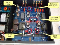
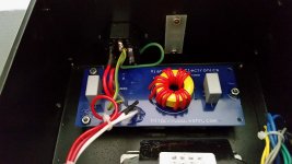
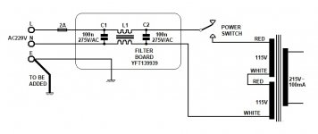
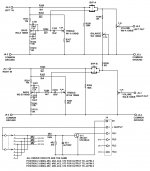
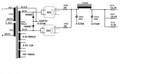
Just started this one and looks like a long haul if I am going to reverse engineer it. Circuits around the internet do not match what I have on the bench, this one uses two Chinese 6Z4 dual rectifiers, each strapped together and both forming part of a Bridge rectifier. The other half of the Bridge is provided by 1N4007 diodes. The main problem I suspect with this particular amplifier is faulty Triode tubes, the owner fitted Mullard NOS tubes which all but one tested as not serviceable. I am uncomfortable with the rectifier circuit where it seems the 8uF maximum reservoir capacitor is exceeded by over 300uF with just a 470 Ohm 2W resistor to limit in-rush current from the poor rectifier tubes. For parts of the world where a good safety supply Ground wire to the metal case is important, there is a naughty bit of construction here. The Earth pin from the power input connector is routed to a filter board and then to the case via compression provided by the boards fixing nuts. I have already placed an additional Ground wire direct from the power input connector to a dedicated Earth Bolt on the underside of the metal case. Naughty one Xiang Sheng!
One of the filter caps had blown as shown by guts emerging from a swollen case so these have been replaced by two quality X2 capacitors.
I think I have managed to reverse engineer the Tone control network. the balance control, volume control and the signal selector switching.
It looks a most daunting task to try to unravel the main circuit board, almost to the point that even after several Rum Toddies I have not yet gained the enthusiasm to do it. Does anyone know if the strange metal box capacitors are any good? They look like NOS oil filled components from WW2.
Attachments
Last edited:
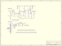
Did a bit more today, probably full of errors but if you have this unit and want to help, just to check the work, it would be appreciated by the many I am sure.
I want to run over the output part again and then try to work out what the two transistors and relay J5 do. Does this thing have a delay? Does it have a dual colour LED on front panel? A yes to both would get me going down a possible circuit route.
I want to run over the output part again and then try to work out what the two transistors and relay J5 do. Does this thing have a delay? Does it have a dual colour LED on front panel? A yes to both would get me going down a possible circuit route.
Attachments
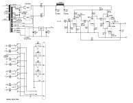
Thanks for the prompt replies lads, I am going to map out that part of the circuit soon. The 2SC331 transistors are quoted as 12V 20mA in the literature I found, there is another 2SC331 but that is a power device. With the flat face towards you and the legs pointing down, they are from left to right Emitter, Base and Collector. I will probably leave the metal can capacitors in circuit but I am going to give them a stringent insulation test first. Hopefully they will pass OK.
Regards
Les
Regards
Les
Last edited:
Interesting what you discover when you unravel the circuit. The earlier sketch is wrong in the output, the feedback resistor is actually sourced from the junction of C103 and C104, C104 is the output coupling capacitor. This means the signal going out has to go through two coupling capacitors. the oil filled one (C103) and then a square Poly one (C104). Maybe they don't trust the NOS oil filled
The HT line also has an odd 22uF/400V (5C5) on it as well as a 100nF 400V (5C3)., presumably to reduce HF Noise?
Also discovered the unit has a heater lift circuit using 5R1, 5R2, 5C4 and a HT Bleeder 330k (5R8). These I shall add to the provisional circuit diagram.
The HT line also has an odd 22uF/400V (5C5) on it as well as a 100nF 400V (5C3)., presumably to reduce HF Noise?
Also discovered the unit has a heater lift circuit using 5R1, 5R2, 5C4 and a HT Bleeder 330k (5R8). These I shall add to the provisional circuit diagram.
> the feedback resistor is actually sourced from the junction of C103 and C104
The NFB from a cathode throws DC on the output of C103. That is rude to the next box in the chain. Double-capping is perhaps the most common fix-up.
Your sketch with the cap in the NFB network leads to a subsonic rise, as the "22K" leg rises in impedance below 7Hz due to 1uFd series.
The NFB from a cathode throws DC on the output of C103. That is rude to the next box in the chain. Double-capping is perhaps the most common fix-up.
Your sketch with the cap in the NFB network leads to a subsonic rise, as the "22K" leg rises in impedance below 7Hz due to 1uFd series.
To get the best clarity overall circuit diagram of the latest 728A model, you can download it direct from here:-
http://www.g4cnh.com/public/overall_circuit.bmp
Might not be 100% but pretty damn close
http://www.g4cnh.com/public/overall_circuit.bmp
Might not be 100% but pretty damn close
- Status
- This old topic is closed. If you want to reopen this topic, contact a moderator using the "Report Post" button.
- Home
- Amplifiers
- Tubes / Valves
- Mods Xiang Sheng 728A