The title is slightly misleading, and I apologize for it: by "discrete", I only mean "not monolithic". The circuit shown is based on a posting by jcx@diyaudio a few years ago, but I cannot locate the original posting - I'd be grateful if somebody who has saved the link can post a follow-up with the link.
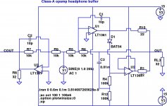
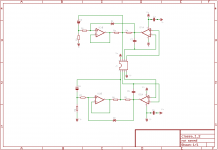
The basic idea behind jcx's topology is the use of two opamps, a master as the voltage-amplifier and a slave as a voltage-follower, with a bootstrapped level-shifter between the two. The output is simply the summation (with current-sharing resistors) of the outputs of the two opamps. This seemingly simple topology accomplishes a great deal of magic by two mechanisms:
1) The output stages of both opamps are biased to Class-A due to the level shifter.
2) The short-circuit current limit is doubled by the use of two opamps.
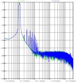
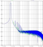
Does it make that much of a difference? Yes, it does - especially when driving low-impedance loads like headphones. The LTSpice schematic shown is a simple unity-gain inverting amplifier with a single opamp (as control with output cout) and two opamps using jcx's topology (with output out). The THD20 FFT is shown for 1V output amplitude into 32 ohms (a typical headphone load).
Result: THD20 is vanishingly small for the jcx Class-A circuit (green curve), and predominantly H2. The single opamp control shows considerable odd-harmonic distortion (blue curve).
The basic idea behind jcx's topology is the use of two opamps, a master as the voltage-amplifier and a slave as a voltage-follower, with a bootstrapped level-shifter between the two. The output is simply the summation (with current-sharing resistors) of the outputs of the two opamps. This seemingly simple topology accomplishes a great deal of magic by two mechanisms:
1) The output stages of both opamps are biased to Class-A due to the level shifter.
2) The short-circuit current limit is doubled by the use of two opamps.
Does it make that much of a difference? Yes, it does - especially when driving low-impedance loads like headphones. The LTSpice schematic shown is a simple unity-gain inverting amplifier with a single opamp (as control with output cout) and two opamps using jcx's topology (with output out). The THD20 FFT is shown for 1V output amplitude into 32 ohms (a typical headphone load).
Result: THD20 is vanishingly small for the jcx Class-A circuit (green curve), and predominantly H2. The single opamp control shows considerable odd-harmonic distortion (blue curve).
Attachments
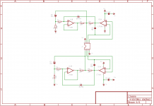
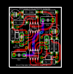
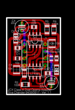
Here's the exported Eagle schematic and PCB layout for a DIP8 plug-in dual-opamp module using jcx's topology. The layout is only a reasonable first pass attempt and is not claimed to be optimal, but seems to be workable. A wide variety of SOIC-8 dual opamps may be used instead of the LT1361 shown. There's sufficient space for premium rail-to-rail bypass caps (e.g. Wima FKP2) as well as bootstrap caps (e.g. Elna cerafines or Rubycon Black Gates).
If there's sufficient interest, I'll probably have a batch of 20-50 boards fabricated, and offered in the group buy section either as bare PCBs or assembled modules.
If there's sufficient interest, I'll probably have a batch of 20-50 boards fabricated, and offered in the group buy section either as bare PCBs or assembled modules.
Attachments
AD8397-class A? - Page 2 - Head-Fi.org Community and the next page in that thread
also: http://www.diyaudio.com/forums/soli...ain-composite-op-amp-circuits.html#post512806 - from which you can see i like multiloop cirucit too, and I have combined both techniques for headphone amps
there is a Class A push-pull region, if sized to the op amp output current limit then the output will always be Class A but wouldn't double the individual op amp current limit
if you just choose "deep Class AB" the output will be Class A for smaller currents and then when the load current exceeds the 2x the bias the 2 op amp output currents will add
Last edited:
with the local feedback cap inside the current sense R you can compensate the amp to be stable with C load - the concern is because the sense R adds phass shift inside the global feedback network and not helped by the direct load ouput Z phase shift that the LT1361 "C load stable" internal compensation addresses
I would choose higher output current op amps over the LT1361 since the specs it excels in aren't that relevant to audio
I would choose higher output current op amps over the LT1361 since the specs it excels in aren't that relevant to audio
The layout is sufficiently generic to accommodate other opamps, compensation caps and current sharing resistors - maybe a THS4031 or LM6172 if the load is a low-Z headphone load. If it's mainly a line-level high-Z load, I'd probably go with the LM4562 or LME49722 for a premium version, and a lowly NE5532 or LM833 for a generic version for CD-player and PC sound-card upgrades, etc.
I just noticed a few errors both in the schematic and layout, which I'll fix in the next iteration.
I just noticed a few errors both in the schematic and layout, which I'll fix in the next iteration.
Updated and corrected errors on schematic; updated SMD PCB layout - most compact version to date with (mostly) 1206-sized parts. I'm still undecided whether to downsize to 0805-sized parts - the Panasonic ECHU capacitors that I'd like to use for rail-to-rail bypass are mostly 0805-sized.
Please post a follow-up if there's any obvious error or must-have feature in the module - the Gerbers will be sent for fabrication within a week or two.
Please post a follow-up if there's any obvious error or must-have feature in the module - the Gerbers will be sent for fabrication within a week or two.
Attachments
For unknown reasons, I didn't get a response from the PCB vendor for the previous version - maybe the per-unit price and quantity was too small to interest him. Anyway, it turned out to be a blessing in disguise - I was able to improve the design.
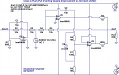
The capacitive bootstrap for the diode level-shifter in the JCX design troubled me a bit - both for the frequency dependence and the capacitor quality/aging issues. I wanted to change the level shifter to a completely non-reactive one, and luckily it was not too difficult.
The first pass used a TL431 2.5V reference and a voltage divider, but it still required a small electrolytic to bypass the TL431. Moreover, the minimum bias current for the TL431 was a bit high and limiting the swings. The Zetex micropower references turned out to be a near-perfect fit - a ZRC250 2.5V reference is shown in the simulation schematic, but almost any voltage (say 1.24/1.25 V) is usable. The minimum bias current for the Zetex parts is spec'ed at 50 uA, and no bypass cap is required.
At THD20 FFT shown is for 10V amplitude into 600 ohms. Vout is the Class-A biased output, and Vcout is the control. The sonics of the composite Class-A opamp (light green curve) turn out to be far superior to the stock LME49860 (LM4562) used as the control (blue curve) - the former shows lower THD as well as a dominant H2 component, while the latter is almost entirely odd-harmonic.
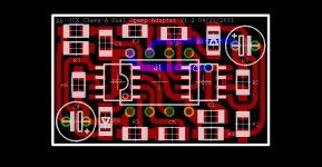
A mostly SMD PCB layout for a dual-opamp DIP-8 module is also shown. If no improvements come to mind in the next few weeks, this will be prototyped and go into production (bare PCBs and/or assembled units will be offered for a group buy sooner or later).
The capacitive bootstrap for the diode level-shifter in the JCX design troubled me a bit - both for the frequency dependence and the capacitor quality/aging issues. I wanted to change the level shifter to a completely non-reactive one, and luckily it was not too difficult.
The first pass used a TL431 2.5V reference and a voltage divider, but it still required a small electrolytic to bypass the TL431. Moreover, the minimum bias current for the TL431 was a bit high and limiting the swings. The Zetex micropower references turned out to be a near-perfect fit - a ZRC250 2.5V reference is shown in the simulation schematic, but almost any voltage (say 1.24/1.25 V) is usable. The minimum bias current for the Zetex parts is spec'ed at 50 uA, and no bypass cap is required.
At THD20 FFT shown is for 10V amplitude into 600 ohms. Vout is the Class-A biased output, and Vcout is the control. The sonics of the composite Class-A opamp (light green curve) turn out to be far superior to the stock LME49860 (LM4562) used as the control (blue curve) - the former shows lower THD as well as a dominant H2 component, while the latter is almost entirely odd-harmonic.
A mostly SMD PCB layout for a dual-opamp DIP-8 module is also shown. If no improvements come to mind in the next few weeks, this will be prototyped and go into production (bare PCBs and/or assembled units will be offered for a group buy sooner or later).
Attachments

- Status
- This old topic is closed. If you want to reopen this topic, contact a moderator using the "Report Post" button.
- Home
- Source & Line
- Analog Line Level
- Discrete dual-opamp DIP08 module (jcx topology)