My latest project. I've seen a few switched attenuator projects, they all use rotary controls, I decided to go with the touch-sense stuff I developed earlier.
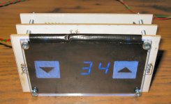
Here you can see the basic idea, a perspex fascia with touch-sense areas engraved in the back side is illuminated from the edge with LEDs. Behind this a 'black' transparency hides the touchsense pads and covers the aperture the IR sensor looks through. Seven-segment displays show the volume setting in this case through the semi-opaque film.
Here's the new assembly:-
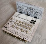
This has 3 PCBs, the horizontal one carries the relays, resistors, relay drivers, latches, audio amps and RCA connectors. The main board is single-sided with numerous wire links.
The vertical board plugged into it carries the 7-segment displays, latch/LED drivers, IR sensor and channel indicator LEDs. This board is doublesided with manually placed vias. I tried creating these with conductive paint as I saw in an internet article, but I reverted to wire as I found the paint unreliable. This was a disappointment, as I could really do without the raised bumps on the touchsense PCB.
w

Here you can see the basic idea, a perspex fascia with touch-sense areas engraved in the back side is illuminated from the edge with LEDs. Behind this a 'black' transparency hides the touchsense pads and covers the aperture the IR sensor looks through. Seven-segment displays show the volume setting in this case through the semi-opaque film.
Here's the new assembly:-

This has 3 PCBs, the horizontal one carries the relays, resistors, relay drivers, latches, audio amps and RCA connectors. The main board is single-sided with numerous wire links.
The vertical board plugged into it carries the 7-segment displays, latch/LED drivers, IR sensor and channel indicator LEDs. This board is doublesided with manually placed vias. I tried creating these with conductive paint as I saw in an internet article, but I reverted to wire as I found the paint unreliable. This was a disappointment, as I could really do without the raised bumps on the touchsense PCB.
w
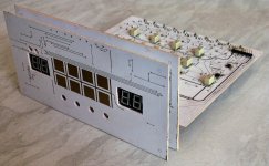
Front view of the assembly, not fully populated at this stage, but I get a chance to verify the board-to-board connector positioning and make sure the displays and LEDs line up with their holes.
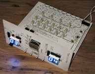
The device is obviously stereo, it offers 0-63 dB of attenuation (plus mute) using 1% precision resistors. The internal impedance is 10k, all the inputs and outputs have T-attenuator pads to allow versatile passive matching to input and output impedances, and in addition there is a relay switched buffer at the input with a high input and 10k output impedance, this can be set up with whatever fixed gain is deemed desirable, the buffers use individual LME49710 opamps, and individual power supplies can be used for these. Here's the next stage of development, I'm using the veroboard circuit to simulate the inputs expected from the touchsense board. Now you can see the 7-segment displays illuminated.
w

The device is obviously stereo, it offers 0-63 dB of attenuation (plus mute) using 1% precision resistors. The internal impedance is 10k, all the inputs and outputs have T-attenuator pads to allow versatile passive matching to input and output impedances, and in addition there is a relay switched buffer at the input with a high input and 10k output impedance, this can be set up with whatever fixed gain is deemed desirable, the buffers use individual LME49710 opamps, and individual power supplies can be used for these. Here's the next stage of development, I'm using the veroboard circuit to simulate the inputs expected from the touchsense board. Now you can see the 7-segment displays illuminated.

w
Both signal grounds are completely isolated from each other and from the digital circuitry.
In order to accommodate the 'bumps' that resulted from using wired vias on the touchsense board, I have had to make an intermediate perspex spacer with holes drilled in it everywhere there is a via. You may be able to see it in this picture.
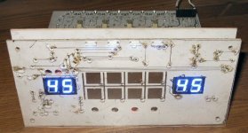
At this stage I have got the touchsense buttons working. These will be left up, left down, channel select (there are 4 channels available), buffer on/off, both up, both down, right up, right down.
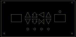
The software remembers settings from channel to channel and retains the settings when the unit is switched on and off. The remote control will additionally offer a standby function. Here is the template for the fascia engraving. The symbols are arbitrary, but have the advantage of looking like they came off a stargate or some such. They're reversed L-R in this picture.
The next task is to make the IR work. I have already done this for 2-function in the previous project with a PIC12F508, now I need to transfer this to 9 functions in a PIC16F690. I'd like to make the IR learn new control codes on command, but I haven't given the pic an LED which would be nice to indicate stages in the learning procedure.
It has been necessary to rewire some of the boards in places, for example I chose to use common-cathode display drivers but I had common-anode displays and wired originally for these, but I am building a second unit for a friend, and these problems will be ironed out on the next iteration.
Next, the enclosure, which will be wood, and fit like a glove.
w
In order to accommodate the 'bumps' that resulted from using wired vias on the touchsense board, I have had to make an intermediate perspex spacer with holes drilled in it everywhere there is a via. You may be able to see it in this picture.

At this stage I have got the touchsense buttons working. These will be left up, left down, channel select (there are 4 channels available), buffer on/off, both up, both down, right up, right down.
The software remembers settings from channel to channel and retains the settings when the unit is switched on and off. The remote control will additionally offer a standby function. Here is the template for the fascia engraving. The symbols are arbitrary, but have the advantage of looking like they came off a stargate or some such. They're reversed L-R in this picture.

The next task is to make the IR work. I have already done this for 2-function in the previous project with a PIC12F508, now I need to transfer this to 9 functions in a PIC16F690. I'd like to make the IR learn new control codes on command, but I haven't given the pic an LED which would be nice to indicate stages in the learning procedure.
It has been necessary to rewire some of the boards in places, for example I chose to use common-cathode display drivers but I had common-anode displays and wired originally for these, but I am building a second unit for a friend, and these problems will be ironed out on the next iteration.
Next, the enclosure, which will be wood, and fit like a glove.
w
Here's the illuminated front panel. Unfortunately the black-printed inkjet transparency came out a bit dotty, you can see this superimposed on the 7-segment displays, I'll make a better one for the final build, but it's necessary to dismantle the whole thing to replace it, any little bit of white dust shows up and it's a pain to keep everything clean. The relative illumination levels of the buttons and the displays seems to have worked out OK though. The colour match is good too. I'm wondering if I should make it dim after a period of inactivity, but there's a resource limitation with the current processors, currently 2 x 16F887s and a 16F690.
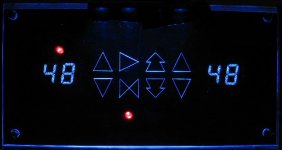
You can see the channel indicator and 'buffer active' LEDs. When the PCBs are assembled into the enclosure the illumination LEDs, mounting holes and perspex edges will be invisible, so the illuminated features will simply emerge from the black background. Part of the challenge has been to create a set of symbols which can be hand-engraved satisfactorily. The entire assembly is hand-made at home, I believe it will be indistinguishable from any professional product when complete. The touch-sense feature took a lot of tweaking of the on/off levels, but the buttons work reliably now with the thickness of the perspex used.
Last night, while cutting panels for the enclosure, I broke the scroll saw blade and it was the only one, so this has held up progress on that, but I got new blades today. The first enclosure will be from 8mm ply, which is not an unattractive material, but I am sourcing some hardwood for the next build.
Now I have to go back to work on the mezzanine board which will carry the transformers and other components for for the digital supply, the independent dual-rails for the buffers and the standby switching. The connector for this is provided on the main board. I have to make the IR remote work too. An aluminium back-plate with piercings for the RCAs, a hard on/off switch and fused IEC mains receptacle will also be required.
w
I built the enclosure over the last few days, I'm pleased with the fit. It's still running off a lab power supply though. I have to order the resistors for the attenuators too, these are all made up from 2 individual resistors so that I can get close to the design values.
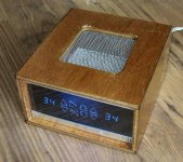
I still have to make a few more bits such as the backplate and the mezzanine board for the PSU, and program the IR decoder.
Computer aided design is wonderful. I've been able to do all this and have the bits fit together without a problem. I had to cut a couple of tracks and install some white wires, but I didn't expect to complete something so complicated without error. I had to push on and get to the construction stage, because I did the design over quite a period, I lost track of which intended modifications I'd completed. Once you get to the point of expecting things to work though, any deficiencies jump out at you.
w
- Status
- This old topic is closed. If you want to reopen this topic, contact a moderator using the "Report Post" button.