Hi,
I’ve searched and read a lot about this, but I’m struggling to find a definitive answer for my particular case.
How does this sound for a grounding plan:
The input selector only switches signal +ve, sends it to the stepped attenuator, then on to the output +ve. The left input grounds are bussed together, along with the left output ground. The right input grounds are bussed together, along with the right output ground. This keeps the left and right grounds and signals completely separate.
Will this work, or do I need to connect these ground busses to the chassis (aluminium) somewhere to avoid RFI? Also, in this arrangement each signal ground is connected to the ground circuits of all the other pieces of equipment currently plugged in to the inputs. Will this be a nightmare for hum? I can’t see an alternative to this though, as I can’t have a separate ground for every RCA connector unless I double up on poles and switch the grounds as well as the +ve. Almost every design of passive pre I’ve seen doesn’t switch grounds though, only the +ve. Confused.
Cheers,
Leon
anything more than monoblock construction requires signal grounds and power grounds to be interconnected at some point.
Read
Audio Component Grounding and Interconnection - diyAudio
thoroughly and go back and pick out the important messages for your intended use.
Only 58k views. There's a lot of Members that refuse to research.
Read
Audio Component Grounding and Interconnection - diyAudio
thoroughly and go back and pick out the important messages for your intended use.
Only 58k views. There's a lot of Members that refuse to research.
Inside a screen the potential is everywhere the same. A circuit completely inside the screen, with no external connections, will not be aware of any electric fields outside the screen. In this situation the screen does not need grounding.
If the circuit has an external connection (and most do) then it becomes sensitive to the difference between its ground and the screen potential. An ungrounded screen then becomes a probe, sensing the external field and passing it on to the internal circuit. As the screen is presumably larger than the circuit, it will pick up interference more effectively than the circuit would on its own because it has a larger capacitance to any external conductor.
If the circuit has an external connection (and most do) then it becomes sensitive to the difference between its ground and the screen potential. An ungrounded screen then becomes a probe, sensing the external field and passing it on to the internal circuit. As the screen is presumably larger than the circuit, it will pick up interference more effectively than the circuit would on its own because it has a larger capacitance to any external conductor.
I still can't see why?
Andrew,
Go back and read the reference you recommended. I don't have a page number, but it's in there.
Take two conductors. Set them at different potentials, by means of two wires to a voltage supply. There will be an electric field between them. Now stretch one of them out so that it begins to enclose the other one. The electric field is still there, although its shape will depend on geometry. Continue stretching until one conductor almost completely encloses the other one, except for a small hole where the wire goes through. The electric field is still there. This is a passive preamp in a metal box. If you vary the potential of the outer conductor then you will induce a current, as the two conductors together make a capacitor.
Now remove the wire from the inner conductor, and close the hole in the outer conductor. The electric field inside the outer conductor vanishes. This is a Faraday screen. Changing the potential of the outer conductor does not affect the inner conductor, as it only ever sees a uniform potential around it and no electric field. Note that it is not closing the hole that makes the difference (we could have left it there, or even drilled more holes), but removing the wire to the inner conductor.
Now remove the wire from the inner conductor, and close the hole in the outer conductor. The electric field inside the outer conductor vanishes. This is a Faraday screen. Changing the potential of the outer conductor does not affect the inner conductor, as it only ever sees a uniform potential around it and no electric field. Note that it is not closing the hole that makes the difference (we could have left it there, or even drilled more holes), but removing the wire to the inner conductor.
fig 3.2-1 shows it.
3.2-2 shows why not to ground the shield.
Going to the output side. figs 3.2-3 to 7 again show why the shield should not be grounded.
The later diagrams show the additional features that must be included if the shield and/or chassis are grounded.
3.2-2 shows why not to ground the shield.
Going to the output side. figs 3.2-3 to 7 again show why the shield should not be grounded.
The later diagrams show the additional features that must be included if the shield and/or chassis are grounded.
Last edited:
That article is about equipment containing mains PSUs, so not directly applicable to a passive preamp.
Some of his advice is incorrect e.g. figure 3.2-4 is not a clean power supply, as it injects charging pulses into a star ground. 3.1-1 is a better PSU, provided it is grounded at the quiet end rather than the noisy end. I don't want to drift off-topic, just noting that if he is wrong on some things he may be wrong on others.
Some of his advice is incorrect e.g. figure 3.2-4 is not a clean power supply, as it injects charging pulses into a star ground. 3.1-1 is a better PSU, provided it is grounded at the quiet end rather than the noisy end. I don't want to drift off-topic, just noting that if he is wrong on some things he may be wrong on others.
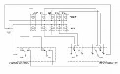
Ok guys I think it'd be a lot easier if I attach a picture. They do, after all, say a thousand words.
The input selector is a single-layer, 2 pole, 6 way elma rotary switch, limited to 4 positions.
For the volume control I'm custom-making a series type stepped attenuator from a twin-layer, 2 pole, 24 way elma rotary switch and a selection of takman 1% resistors.
I'll be mounting the switches at the rear of the enclosure using extension shafts to keep all wiring as short as possible.
Any comments/suggestions/criticisms of my design will be greatly appreciated.
Thanks,
Leon
Attachments
The passive attenuator and selector switch are inside a metal chassis. That chassis has no mains electricity inside it.
The only connections to/from that chassis are via the interconnects.
The chassis does not need to be grounded. It is a shield. It is simply connected to the Signal Ground, but certainly not to the mains supply Ground.
The only connections to/from that chassis are via the interconnects.
The chassis does not need to be grounded. It is a shield. It is simply connected to the Signal Ground, but certainly not to the mains supply Ground.
The chassis should be grounded to signal ground on one channel. Each volume control should be grounded to its own channel signal ground. I am not sure whether to connect the left and right signal grounds together here. They will probably already be connected together at sources and main amp anyway.
In theory there is a problem with ground loops formed by left and right channel cable screens, but provided the area of the loops is small it should be OK.
In theory there is a problem with ground loops formed by left and right channel cable screens, but provided the area of the loops is small it should be OK.
In theory there is a problem with ground loops formed by left and right channel cable screens, but provided the area of the loops is small it should be OK.
The loop area may likely not be small enough to avoid a problem in this situation. The answer is to keep the current in the loop from creating a noise signal that is further amplified. Leach, for example, gave an example of how to reduce this problem by connecting the input screen of one channel to the input of the other instead of the PCB. This keeps the the noise loop out of the signal loop.
I think it would help the discussion to be clear on what ground is being discussed, i.e., safety earth vs. signal ground reference.
For the screen/chassis to be most effective, the signal reference should be connected to the screen/chassis. This does not mean that it must be connected to earth to work as a screen. However, for safety reasons, the chassis may be REQUIRED to be connected to earth. By default, this means the signal ground is also connected to earth. So given that situation, one must follow certain guidelines to keep the problems away.
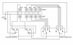
Ok thanks again guys for your input, it's very much appreciated. Check out Mk. II.
As per DF96's advice, I've connected the left and right volume GND's to their respective signal reference busses. These busses are then connected to the chassis at a single point: the chassis ground pin. I figured this is the only option, since to have only one channel's signal reference connected to the chassis and the other channel isolated didn't seem right. Although I have to admit I'm not basing this on any science.
In response to pooge's good suggestion of clearly defining just which "ground" we are talking about, I'm concerned here with signal reference only. Since this is a passive preamp, there is no mains electricity involved whatsoever. The only inputs are the RCA left and rights at line-level, and the only output the equivalent line-level RCA outs.
This is partly why I'm struggling to find the imformation I need; most, if not all, information available is concerning safety grounds and PSU's.
Anyway, cast an eye over mk. II and see what you think. I've included a GND from the input selector switch, connected to the chassis ground pin. Again, I don't know if this is correct.
Is it obvious I have absolutely no idea what I'm doing? Ha ha ha. Come on, we've all gotta start somewhere.
As always, your comments are greatly appreciated.
Cheers,
Leon
Attachments
- Status
- This old topic is closed. If you want to reopen this topic, contact a moderator using the "Report Post" button.
- Home
- Source & Line
- Analog Line Level
- Passive Preamp - Grounding plan