I am starting a new thread about this circuit board, which I initially posted about in another thread on some modular active crossover PCBs that I am also developing.
As a speaker building hobbyist, I have wanted to have a flexible circuit board that I could use to build a variety of filter types. Since I didn't find anything available, I decided to design and build my own. It has been invaluable to discuss the designs and the capabilities here, so I am inviting people to join in. Hopefully I will end up with something that many people could find useful, too.
I call this the "Universal Filter Board" because you can use it to implement pretty much any type of filter that you would want to use for loudspeaker crossovers. These include:
The circuit uses a single dual op-amp and there are two independent sections on the board, each using one of the amplifier's in the IC. Each PS rail is decoupled to ground at the IC pin and there is a rail-to-rail decoupling cap as well if you would rather decouple that way. Inputs are via miniature screw terminal blocks or you can solder wires directly to the signal I/O and PS pins.
I have built and tested a prototype of this board that has slightly different functionality, and the performance was pretty good. This latest revision adds the jumpers, rail-to-rail bypassing cap, and expands the range of functional capabilities. After some more review of the PCB design, I plan to get a few prototypes made to test out this revision of the design. I will post more info when I have it.
-Charlie
As a speaker building hobbyist, I have wanted to have a flexible circuit board that I could use to build a variety of filter types. Since I didn't find anything available, I decided to design and build my own. It has been invaluable to discuss the designs and the capabilities here, so I am inviting people to join in. Hopefully I will end up with something that many people could find useful, too.
I call this the "Universal Filter Board" because you can use it to implement pretty much any type of filter that you would want to use for loudspeaker crossovers. These include:
- First Order buffer or gain stage (inverting or non-inverting)
- First order HP or LP filter (inverting or non-inverting)
- Second order HP or LP filter (inverting MFB topology or non-inverting Sallen-Key topology)
- Second order HP and LP filter + notch
- Notch filter
- Third order HP or LP filter (inverting MFB topology)
- First order all-pass (delay) filter
- Second order all-pass (delay) filter (Steffen or Delyiannis topology)
- General biquadratic filter (Friend’s SAB topology, for LT biquad)
The circuit uses a single dual op-amp and there are two independent sections on the board, each using one of the amplifier's in the IC. Each PS rail is decoupled to ground at the IC pin and there is a rail-to-rail decoupling cap as well if you would rather decouple that way. Inputs are via miniature screw terminal blocks or you can solder wires directly to the signal I/O and PS pins.
I have built and tested a prototype of this board that has slightly different functionality, and the performance was pretty good. This latest revision adds the jumpers, rail-to-rail bypassing cap, and expands the range of functional capabilities. After some more review of the PCB design, I plan to get a few prototypes made to test out this revision of the design. I will post more info when I have it.
-Charlie
Weirdly enough active filters don't get attetion/support here ")
All-in-all they are superior, easier to play with, and give much more versatility than passive filters. And they are cheaper even with good performing amplifiers on their outputs.
Maybe that's besause of "voodoo" of analog low-signal active circuits where you have to design (calculate) them yourself?
Probably "many opamps" thing is the main turn-off...
Well i have to take my words back, as i've somehow overlooked your previous threads
They have some interesting discussions, i'm studying them right now
Too bad i'm doing this after i finished my crossover board
By the way, it seems you have lots of experience in active filters - have you ever compared the performance of different filter topologies, i.e. MFB/SK/State Variable/substractive?
this sounds excellent! might i suggest multi-stage buffering? a JFET buffer followed by an op-amp buffer can work wonders. check out this link for some useful tidbits AMZ Basic Buffers
this sounds excellent! might i suggest multi-stage buffering? a JFET buffer followed by an op-amp buffer can work wonders. check out this link for some useful tidbits AMZ Basic Buffers
The circuit is pretty much designed... so I am not planning on adding any more buffer stages. The link you gave is more for guitar preamps... The circuit should perform fine.
I am currently doing some modeling of the biquad circuit to make sure that you can implement the Linkwitz Transform using the Friend SAB circuit. I am also trying to incorporate the sensitivity of the circuit(s) to component tolerance in a design spreadsheet for each topology. I did the with SL's LT circuit recently, by implementing something like Monte Carlo analysis in Excel.
After making these last design changes, I have definitely been able to simplify the PCB layout since the last iteration. This freed up the room to add the rail-to-rail bypass cap, and to allow for a lot more breathing room near the edge of the PCB. This might just become my go to PCB for crossover design because of its flexibility. For high Q HP/LP stages and notches, I may instead use a PCB based on a SVF biquad (my modular filter board), since the circuit less sensitive to component variations and can handle high Qs without a problem.
-Charlie
Well i have to take my words back, as i've somehow overlooked your previous threads
They have some interesting discussions, i'm studying them right now
Too bad i'm doing this after i finished my crossover board
By the way, it seems you have lots of experience in active filters - have you ever compared the performance of different filter topologies, i.e. MFB/SK/State Variable/substractive?
Although I have read about some of the relative advantages/disadvantages of SK and MFB filters, I have not actually tried to compare them side by side. SVF designs will likely be better in terms of adjustability and have a lower sensitivity to component value variation, but they are more complex and costly.
-Charlie
Friends Biquad for Linkwitz Transform
Today I managed to figure out how to use the "Friend's biquad" circuit to implement a biquadratic filter function, e.g. to use it as a "Linkwitz Transform". Since this is one of the circuit topologies that my "Universal Filter Board" can take on, this makes the PCB super flexible because I was expecting to have to design yet another PCB for the LT circuit but now it looks like I can just use the UFB! Awesome.
In the next couple of days I hope to do some Monte Carlo type analysis of the circuit sensitivity. Since there are several adjustable parameters in the design of Friend's circuit, I need to see how to minimize the response deviation. I also want to see how sensitive the response is to resistor and capacitor tolerances.
Anyway, that's today's update. So far so good!
-Charlie
Monte Carlo sensitivity analysis results for Friend's biquad
After a few hours of plugging away at it, I completed my sensitivity analysis for the Friend's biquad circuit. This included calculating the exact component values required, then looking up the nearest "real world" component value (e.g. the E96 or E192 series resistor value), and then doing a sampling process to get a trial value within +/- % tolerance of the "real world" component value. This is the best way that I can come up with, using Excel, to model what happens when you build the circuit using real resistors, that can only be purchased in discrete values, and which have some range of values around that discrete value as described by the tolerance of the resistance value.
To get an assessment of the sensitivity of the response to these "real world" trial component values, 1000 calculations of the same transfer function are performed, and the min and max deviation from the predicted response for the discrete component value with zero tolerance are determined. This allows me to create a kind of "confidence band" of expected responses.
What I found was that I could get the response to be within about +/-0.5 dB of the target, and the level of deviation was often less. To get this level of performance, I did need to use E192, 0.1% tolerance resistors and 1% capacitors, however these are readily available and not really all that expensive. The circuit is very flexible about the capacitor value chosen, since you can just do impedance scaling of all the resistors,
So, bottom line is that I can pretty much do anything I need with the Friend biquad circuit. It's just like Sigfried Linkwitz's "Linkwitz Transform" circuit, except it uses one less capacitor (two versus three for SL's circuit). Both are single op amp biquads. Down the road I would like to do this same sensitivity analysis of this circuit, targeted for high-pass notch and low-pass notch circuit, which are used to construct elliptic filters.
The noteworthy thing about the Friend circuit, and what some might consider a drawback (but I don't), is that it can not generate a response that has any gain at all, for any frequency. For example, this means that, a circuit that boosts the low frequencies for a subwoofer to extend the passband, the Friend circuit is cutting the higher frequencies. In constrast SL's LT biquad will boost the lower frequencies. In either case, the circuit shape remains the same, but it's something to keep in mind with the Friend circuit.
Next up: modeling Steffen's second order All-Pass filter (unity gain).
-Charlie
All pass using circuit of Steffen
Today I figured out the design for the second order all pass (delay) filter based on the circuit of Steffen. This circuit has the main advantage that it has 0dB of gain or loss for all frequencies, regardless of the delay. This overcomes a major issue with some other all-pass circuit topologies, that can have 10dB or more of loss, and so have to be followed with a big gain stage.
The circuit design is actually pretty simple, once you figure it out. There are only seven components and an op amp. The circuit can be built on my Universal Filter board.
I've been looking for something like this for analog delay for awhile. The other option that I have been considering is using an Antoniou biquad as an all-pass filter. This has a gain of 2 V/V but that is no big deal and can be paired with a 1:1 voltage divider at the input to restore unity gain overall.
Speaking of the Antoniou biquad, I ran across some discussion of using a generalized form of the 2 op-amp version of this circuit to create LP, HP, BP, notch and AP, depending on how you configure it. I realized that with one or two tweaks I can build this topology on my First Order Building Block circuit board, so I hope I can figure out how to modify that circuit's PCB layout to accommodate the additional components. That would give me multiple options for each filter type. The whole goal of this experiment in circuit board planning is to make up a small number of boards that can be built up in to whatever type of block might be needed for loudspeaker crossovers, which is my main interest (active loudspeakers). So far, it looks like these two boards might be all I will ever need.
-Charlie
sensitivity analysis results for Steffen all-pass filter
I decided to do a "quickie" sensitivity analysis on the Steffen circuit without going through the hassle of creating a slow spreadsheet that runs 1000 random trials. After all, this is a pretty straight forward circuit. What I found was pretty encouraging.
With 1% resistors and capacitors, I can keep the amplitude flat within about +/-0.2 dB and the delay only varies by about +/-1%. If I change the resistors to 0.1% tolerance, the amplitude variation drops to about +/-0.05 dB and the delay variation drops to about +/-0.15 %. Interestingly enough, the capacitance tolerance has much less effect than the resistor tolerance. If I use 0.1% resistors but 5% caps, the variation is only +/-0.05 dB in amplitude and +/- 0.15% for the delay, so it looks like the resistors control all the variation and the caps are not much of a factor. Weird.
Anyway, this looks like a very reliable and workable circuit for implementing a second order analog delay stage. I'm not sure why it isn't more commonly used.
-Charlie
correction to Steffen sensitivity analysis
In the last post, I mentioned that the Steffen circuit was very insensitive to the tolerance of the capacitors. This was bothering me all night so I went back and took a look at my calculations. I mistakenly used the "ideal" value of the caps in the sensitivity calculation, instead of the one that varied in randomly within +/- tolerance of the ideal value. Once I did this it was clear that the cap tolerance does indeed effect the overall response, so I thought I would post an update about it.
The capacitors in the circuit seem to have about the same effect on the overall accuracy of the response as the resistors. With 1% caps and 0.1% resistors, the amplitude response is within about +/-0.1 dB and the delay within about +/-1 percent of the "target" response. Using 2% tolerance caps and 1% tolerance resistors, the amplitude is within about +/- 0.2dB and the delay within about +/-2 percent. This is still very good performance.
In the analysis of this circuit, I used a "quickie" sensitivity analysis method. I randomly sample component values from the interval mean +/- tolerance, and report the extreme values encountered, which is really a worst case scenario. Real component values are more likely distributed in a Gaussian fashion around the mean, and one typically reports a few standard deviations away from the mean when doing a statistical analysis. Roughly translating my "quickie sensitivity analysis" results in to that format might mean that the deviations from ideal are closer to half of what I reported above, which is very good.
-Charlie
Today I figured out the design for the second order all pass (delay) filter based on the circuit of Steffen. This circuit has the main advantage that it has 0dB of gain or loss for all frequencies, regardless of the delay. This overcomes a major issue with some other all-pass circuit topologies, that can have 10dB or more of loss, and so have to be followed with a big gain stage.
The circuit design is actually pretty simple, once you figure it out. There are only seven components and an op amp.
Is there info on the net for this topology regarding circuit, calculation of values etc?
reference for Steffen all-pass filter circuit
The best reference for this circuit, including how to calculate values, is this journal article:
I am not sure if you can access this on the web. I found it in my local University library. It also has the circuit and calculation method for Friend's biquad circuit. You will need to be able to understand and manipulate transfer functions in order do actually do any of the calculations and come up with components values.
-Charlie
Is there info on the net for this topology regarding circuit, calculation of values etc?
The best reference for this circuit, including how to calculate values, is this journal article:
J. J Friend, C. A. Harris, and D. Hilberman, "STAR: An Active Biquadratic Filter. Section," IEEE Transactions on Circuits and Systems, CAS-22 (February 1975), pp. 115-211.
I am not sure if you can access this on the web. I found it in my local University library. It also has the circuit and calculation method for Friend's biquad circuit. You will need to be able to understand and manipulate transfer functions in order do actually do any of the calculations and come up with components values.
-Charlie
ok, thanks.
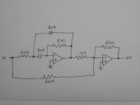
I will stick with the attached topology, for now.
Regarding this shown topology, does it need a HF stability cap, as per the 1st order allpass? (and where is its placement)
With the values shown, how is the input impedance calculated?
Thanks.
I will stick with the attached topology, for now.
Regarding this shown topology, does it need a HF stability cap, as per the 1st order allpass? (and where is its placement)
With the values shown, how is the input impedance calculated?
Thanks.
Attachments
Henry8,
Jeff Macaulay uses this scheme for an equalised subwoofer in "Feel the bass", Electronics World+Wireless World, August 1995, pages 636-640, the second op-amp having a capacitor across the feedback resistor to make it an integrator. Some details for calculation are provided. PM me with your email to get the article.
Jeff Macaulay uses this scheme for an equalised subwoofer in "Feel the bass", Electronics World+Wireless World, August 1995, pages 636-640, the second op-amp having a capacitor across the feedback resistor to make it an integrator. Some details for calculation are provided. PM me with your email to get the article.
Highpass-notch and Lowpass-notch filters designed
Today I created a spreadsheet for calculating the component values for the highpass-notch and lowpass-notch filters that can be created using my Universal Filter board. These filters are useful for creating more complicated ones that require stopband zeros, such as the Chebyshev type II and Elliptic/Cauer filters. There is also another type that is created by adding stopband zeros to a Bessel filter to increase the selectivity/stopband attenuation, but have very good transient response like the Bessel filter. I am very interested in the latter.
These were pretty easy to design, using some procedures that I found in a text book (Design and Analysis of Analog Filters by L.D. Paarman). I plotted the frequency and phase response of the filters, implemented with the closest E96 resistor values and exact capacitor values and it looks pretty good. Because these filters are implemented with a SAB and MFB topology, there is not good control on gain in the passband. You sort of have to live with what you get. I am going to see if the gain can be scaled somehow, but I assume it's not possible in general.
Once thing that I am very much interested in doing (and is next on my list) is seeing how sensitive the circuit is to component tolerance. I have read that these building blocks ARE pretty sensitive so I need to do the same Monte Carlo type modeling that I did for the Friend Biquad circuit. This should make it more clear what I can expect from a real circuit. Hopefully I can do that in the next day or two. I will post my findings here when I have them.
-Charlie
update on HP+notch and LP+notch MFB circuit sensitivity
Well, I finally got around to doing the sensitvity analysis for the highpass-notch and lowpass-notch MFB circuits that I have designed, so I am posting this update to the thread.
I pursued a similar path to get the sensitivity of the circuit to real components (picked from E96 or E192 series values) and their tolerance level (e.g. 1%). I simulated the random values that would be expected within +/- tolerance of the "best fit" value from the series, e.g. if the exact resistor value needed to create the circuit was 10,012 ohms, the value 10k was selected. After selecting this "best available" mean value for all the components, I then generated 1000 random values within +/- tolerance of that value and calculated the resulting circuit performance. From the 1000 trials, I find the min and max circuit performance for each frequency and plot that as a sort of confidence band around the "target" response.
What I found was this:
The most sensitive region is the notch. A deep notch is only achieved with tight tolerance components, but 1% resistors and 2% capacitors seem to still give notch depths of at least 40dB on average and to me this is good enough for crossover work. Away from the notch, the frequency of the circuit follows the target quite closely, within about +/- 0.5 dB near the notch and +/-0.1dB farther away from the notch. This is pretty good performance, and was achieved with E96 series 1% tolerance resistors and 2% tolerance caps. Only in the bottom of the notch did the response vary more than this.
Note I did not do any kind of amplifier sensitivity analysis, however I do not believe this to be of concern for audio frequencies using modern op amps.
Now that I have a good understanding of what I can expect from these circuits, I can start planning on using them to build crossovers using elliptic filters!
-Charlie
- Status
- This old topic is closed. If you want to reopen this topic, contact a moderator using the "Report Post" button.
- Home
- Source & Line
- Analog Line Level
- Active Filter, Delay, and LT circuit board