After messing around with it trying out different combinations I’m finding that a 1.5 kOhm attenuator would be easy to do, all the resistors I’d need are readily available and I can easily get a nice attenuation curve down to -60dB. This appears a good compromise.
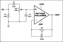
Leon, go ahead with 1,5KΩ. Based on my experiments, i strongly suggest a 1KΩ attenuator (if you can obtain it). With a function generator and an oscilloscope, you could observe how much is affected the signal from the attenuator. You have to inject a square wave of 10KHz in the input of amplifier thru the attenuator, and with the oscilloscope connected at the output of amplifier you could observe if there is overshoot when you turn the attenuator in middle places (from 20% up to 80%) where it works like a voltage divider and affects the Zin of amplifier. Only a 1 to 2KΩ potentiometer does not causes overshoot. Unless, you have to connect compensation capacitors between the output (wiper) of attenuator and GND. Values between 22pF up to 220pF can eliminate the overshoot in the cost of a lower bandwidth. You can see an example in the attached picture, where a 22pF capacitor eliminates the overshoot caused from a 100kΩ pot in a voltage follower circuit.
Attachments
Leon, go ahead with 1,5KΩ. Based on my experiments, i strongly suggest a 1KΩ attenuator (if you can obtain it). ...
The Warpspeed operates with its Zin at 1.1kΩ at its midpoint (-6dB). At my listening levels (9:00 thru 1:00) pretty much varies between 1k thru 2k even with different Source Zout from 200Ω to 900Ω. In my experience, the sweet spot indeed!
I just posted an updated Excel chart here with measured data verifying computed data here...http://www.diyaudio.com/forums/anal...optocoupler-volume-control-9.html#post2509261
Can some please give me the formulae for calculating input impedance and output impedance for a single voltage divider, with the Rx being the resistor at the input Ry the resistor between the output and gnd?
I'd like to calculate Zin and Zout for this attenuator before I buy any parts, but I can't find the relevant formulae anywhere. I was actually under the impression that a series stepped attenuator always maintained a constant Z, regardless of switch position. Now I know it varies, I'd like to do a few calcs.
Thanks,
Leon
I know its stepped, but think of it as a pot for the moment. Whatever is below the wiper is in parallel with the amplifier impedance, so calculate that. Add that to whatever is above the wiper and that's your divider input impedance (or at least resistance). For output impedance, parallel whatever is below the wiper, with whatever is above. Include the amplifier in parallel with the bottom, and the output impedance of the preamp in series with the top. Hopefully that very non-rigorous verbal description helps!
Conrad
Conrad
OK, here we see the source impedance RS, the attenuator (RX + RY) and the load impedance RL. Taking a minimalistic view, we might say that the input impedance of the attenuator is RX + RY, and the output impedance is RY.

Taken in isolation the source sees the attenuator, RX + RY. If taking into account the load, the source sees RX + (RY || RL).
|| means 'in parallel with'.
The current in the circuit I = V / (RS + RX + (RY || RL)). This enables you to calculate the voltage drop across, and current through all the resistances, whether discrete components, or characteristics of the source and load.
It's normal to calculate a source resistance by measuring the open circuit voltage and then the voltage across a known load. Knowing that the voltage is being split between the source resistance and the load, it becomes possible to calculate the source resistance. The meter is taken as having infinite resistance (although this may not be an acceptable approximation). This means that there is no current (!) through the source resistance while measuring, and consequently no voltage drop across it.
The load sees RY, but this doesn't make much sense without the source connected, in which case the load sees RY || (RX + RS). Voltage sources have a very low impedance, looking at the junction of RX, RY then there are 2 parallel paths to ground, the one through RY and the one through RX, RS and the voltage source.
w
OK thanks fellas. I've added to my spreadsheet 2 more columns, Zin and Zout.
For Zin I have "Rx + ((RL x Ry)/(RL + Ry))"
For Zout I have "(Ry x (Rx + Rs)) / (Ry + Rx + Rs)"
Where Rx is everything above the wiper, Ry is everything below, Rs is the output from my soundcard (32 Ohms) and RL is the input to my power amp (15 kOhm).
With Rx + Ry = 1.8 kOhm, my Zin and Zout have now been calculated, but the numbers surprise me slightly.
Zin is 1800 Ohm at mute and remains at this maximum value from -60 dB up to -37 dB. Here it begins to fall, slowly at first but with a rapidly increasing negative gradient, finishing at 1607 Ohm at 0 dB. I had no idea what to expect but this seems feasible.
Zout, however, is slightly curious. Hopefully someone can explain. It starts at 0 Ohm at mute, then 1.8 Ohm at -60 dB, 3.6 Ohm at -54 dB. It seems to follow a pretty tidy positive exponential from 0 Ohm at mute, up to a maximum of 458 Ohm at -6 dB. It then extremely rapidly falls away: 388 Ohm at -3 dB, finally down to 31.4 Ohm at 0 dB.
Why the sharp peak at -6 dB?
Also, is my maths correct?
Thanks guys,
Leon
Hi,
I don't know about you or other Members, but I find your naming convention odd.
Zin = Power Amp input impedance.
Rs = Source output resistance.
Rup = everything above the wiper (except Rs)
Rlo = everything below the wiper
Your first formula is correct and becomes
Rin = Rup + Rlo//Zin = Rup + {(Rlo*Zin)/(Rlo+Zin)} :1
I can visualise where each term comes from.
It's not important that we can decipher your naming convention, but think about yourself looking up this spreadsheet in 6years time.
Yes at high attenuation the pot provides almost the whole input impedance seen by the source.
At near full volume the Zin of the amplifier reduces the apparent Rin of the pot. This is particularly important when the ratio of pot:Zin becomes closer to 1:1, i.e. a high pot value followed by a low Zin becomes worthless at near full volume.
I have not converted your second formula so can't comment on it's accuracy.
However, that -6dB peak is exactly what we expect for a worst case source impedance seen by the receiver, when the volume pot is set to half maximum.
Last edited:
Sorry to cause confusion. I'm new to all this, and obviously not yet familiar with all the nomenclature.
My second formula, according to your labels is:
Rout = ((Rlo x (Rup + Rs)) / (Rlo + Rup + Rs)
From now on I'll adopt the nomenclature you've described.
You've given me confidence that my calcs are correct though, so thanks very much. It's a reassuring find, since my Zin is 33 times my Rout at worst case, and my Rin is 50 times my Zout at worst case too! So I've nailed the "at least 10 times" rule.
Awesome, thanks very much.
I still don't quite get why the Rout peaks at -6 dB though, but I'm not particularly bothered why, it's probably over my head. Just as long as that's normal I'm a happy bloke.
Gonna get these parts bought now and get soldering!
Thanks for all the help everyone, last week I knew nothing about this, and now I'm in a position to start building.
Leon
Hi,
don't simply accept my suggestions for term names.
Use names that mean something to you. Something that will be easy to remember and can be applied consistently in different situations.
This was/is particularly important when programming. After you have written half a dozen programmes each with over a couple of hundred lines. When you look back will it still make sense, even years later?
Try to check the current capability of your 32ohm source.
Low impedance does not equal high current capability.
Check the open circuit voltage, into a 10M voltmeter, try stepped test loads, 100k 10k 2k 1k. Does the output impedance appear to hold steady for all current outputs?
Alternatively, test output distortion into a variety of test Loads. Is there a pronounced change in slope of distortion vs output current?
Last edited:
- Status
- This old topic is closed. If you want to reopen this topic, contact a moderator using the "Report Post" button.
- Home
- Source & Line
- Analog Line Level
- Stepped attenuator - getting the impedance right