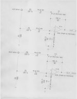
I have attached 2 schematics ( one borrowed , one done by an old acquaintance) for a balanced line driver. I need two things. What can I do to improve them for noise performance? We built the BLD REV.pdf as shown on a PCB layed out at the local tech skool. The sucker was ok, but I got lots of hiss and noise in my car amp and some buzzing(grounding?) It was also very noisy when just driven from my home preamp ( no dc coupling in car)
The second circuit I do not understand where the +/- legs are for the output..
Which circuit would you use and what improvements can we make?
I'll bread board the next unit and then have a professional board done when I'm happy.
The criteria is super low Thd and noise. I intend to use this line drive in both my car and home( I got a long cable runs in both and my gear will accept balanced inputs). I've searched the forums but I must be looking in the wrong place I guess. I want to isolated I/O to eliminate as much noise as possible and ground contamination and a minimum gain of 12 db.. my pres only put out between 1-2 V.
Thanks for time in advance.
BUBBA the electrified gearhead.
PS I have samples of AD8599, LM4562, OPA1642, TLE2072 and 1 set of OPA627 and opa1612 I assume a 10K input impedance would be "normal and 600ohm on the outputs?
Everything I've read and from some previous circuit swapping has me favoring the 8599 but I may be totally clueless here.
Attachments
Last edited:
oops
ok been studying this and I need help..I;m not sure what would constitute the best balanced circuit, but I realized one of my circuit scans sucked so I'm reposting it. really just need some general guidance.. I'm not a circuti designer but I can do good board layout, understand the basics of decoupling and filter caps and general stuff but actually making the circuits work..I'M LOST..thanks
ok been studying this and I need help..I;m not sure what would constitute the best balanced circuit, but I realized one of my circuit scans sucked so I'm reposting it. really just need some general guidance.. I'm not a circuti designer but I can do good board layout, understand the basics of decoupling and filter caps and general stuff but actually making the circuits work..I'M LOST..thanks
Attachments
I DID PROBLEM SOLVED..THANKS LUKUS!!!!
YES I DO PRO GEAR..A I undertstand the need for balanced impedence, THAT'S WHY THE FIRST CIRCUIT HAD ME KINDA BAFFLED.
yes I posted the wrong circuit on the 2nd one.. one output would mean single ended right>>LOL thanks for the ref to the AD-SSM too..I'll read that.!
thanks guys.
YES I DO PRO GEAR..A I undertstand the need for balanced impedence, THAT'S WHY THE FIRST CIRCUIT HAD ME KINDA BAFFLED.
yes I posted the wrong circuit on the 2nd one.. one output would mean single ended right>>LOL thanks for the ref to the AD-SSM too..I'll read that.!
thanks guys.
- Status
- This old topic is closed. If you want to reopen this topic, contact a moderator using the "Report Post" button.