Hi all
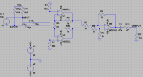
Many years ago I built this microphone preamp for my Behringer ECM8000 mic. It works well but I find it a bit noisy. That's why I added the 100pF caps C8 and C9 but it is still a bit too noisy.
Any ideas how to improve noise without mayor modifications?
Maybe another opamp?
Thanks")
Lee
Many years ago I built this microphone preamp for my Behringer ECM8000 mic. It works well but I find it a bit noisy. That's why I added the 100pF caps C8 and C9 but it is still a bit too noisy.
Any ideas how to improve noise without mayor modifications?
Maybe another opamp?
Thanks
Lee
Attachments
Not a whole lot wrong. 5532's are not usually a problem. If the 100k resistors are carbon comp or carbon film you might change them for metal film. I find the cheap multicomps house brand from farnell in the 2 and 3 watt size I have been buying have been just fine. The higher the value of the resistor, the more noise it produces. I think you had some 68K's, you might do them to. Don't know the lower watt resistors are a problem, just I buy resistors rated 500 V up in case I use them on a tube circuit. I buy a dozen at a time, and put them away. Been drawing on my stocks of 1960's RS grab bag resistors too, the military spec metal film ones anyway.
The pinout is of 1/2 of a DIP amp. I hope you have used the other half for the other mike, or shorted out the input with a resistor? 6,5 are inputs. and a resistor minus input to minus power to disable it if not used.
100 pf is a pretty wild anti oscillation resistor around the feedback resistor (output to minus in). I've been getting away with disc caps marked "22" which might be 22 pf, but you never know about R**** S***** grab bag stuff.
You might also put 0.1 uf disc cap across the back of the socket 8 to 4, if you don't have one within an inch of the IC across the power supply rails. With no disc on power supply, and no feedback cap, my 33078 was oscillating at 1 mhz at gain 50. 33078 is about as fast as a 5532.
Lots of counterfeit stuff is sold on E-bay etc. Maybe your 5532's are really something else. Get some DIP 5532's from farnell or mouser, or 33078's like I got, from a major manufacturer guarenteed. Buy some phosphor bronze sockets while you are at it, to try different things.
Last edited:
As Lee uses 0.1% resistors throughout the amplification chain it has to be asumed that these ar MF resistors. CFs do not come in that tolerance.
Lee does not state what "a bit noisy" means in -dB or uV. My bet would be the 5532. I would also look at the system gain set-up. Maybe more gain (now only 40dB) in the pre-amp and less in the next stages may help.
E
Lee does not state what "a bit noisy" means in -dB or uV. My bet would be the 5532. I would also look at the system gain set-up. Maybe more gain (now only 40dB) in the pre-amp and less in the next stages may help.
E
Thanks for all the input.
Good to hear the circuit isn't bad altogether. This was what I was concerned about the most.
As mickeymoose pointed out the resistors should be okay.
But the high value causes noise that cannot be avoided easily.
I'm not sure about the input impedance anyway. Is it the two resistors to ground (R7,R8) and thus 10k or is it the amplifiers input impedance (~1k) or both in parallel?
The unused opamp has it's input shorted together with wire but left floating. Maybe this is not the best configuration?
I agree the 100pF caps are a bit high and they ceramic which isn't the best choice for sure but they were at hand when building. Maybe I will upgrade to a lower value mica type.
The IC socket has the 100nF cap included.
The 5532A is almost sure to be genuine since I buy from reputable distributors only.
After reading a bit on the forum I think about giving the LM4562 a try. Looks promising on the first glimpse.
Well, I can't express noise in numbers but for my personal taste it is a bit noisy. I observed that noise drops considerably with the mic disconnected. This means the mic is even more noisy.
The following stage was either a line input of a cheap sound card or the active crossovers input. The gain of 40dB seems to be sufficient for me.
The goal of this project was to build a battery powered mic preamp and the constrained space didn't allow for an instrumentation amplifier setup which should perform much better.
I think I'll play around with it a bit and for the case I succeed to lower the noise I'll let you know.
Thanks so far.
Lee
yes, nail down the other side of op amp to power minus or plus through a resistor to make sure it doesn't oscillate. LM4562 has delightful specs. TI RC4562, NJM4562 are different parts with poorer specs than even the NJM4560 that Peavey used in the 1998 era for premium priced products. The noisy mike doesn't surprise me. Behringer stuff doesn't get much here on the resale market.
Oops! 10 blind mice!
As drawn the circuit should not work at all. No split power-suply and all is ground referenced. E
My thoughts, exqctly. The negative half-cycle of input signals will drive the op-amp's inputs below ground, no doubt violating the common-mode range specification for the device. I don't know if this is causing the noise problem which you believe the circuit has, but as a test, try creating a bipolar supply by making ground the node mid-way between the four batteries. Disconnect mic power from the circuit and use a separate battery string to power the mic, not forgetting to then connect that second battery string to the circuit ground.
Ouch! You're so right!
Fixed it and noise is gone completely. Sounds much better now without the negative halfwave cut off.
Somehow I thought it was possible to operate an opamp with a single supply and the output at half the operating voltage after I saw this schematic:
Fixed it and noise is gone completely. Sounds much better now without the negative halfwave cut off.
Somehow I thought it was possible to operate an opamp with a single supply and the output at half the operating voltage after I saw this schematic:
Attachments
Ouch! You're so right!
Fixed it and noise is gone completely. Sounds much better now without the negative halfwave cut off.
Somehow I thought it was possible to operate an opamp with a single supply and the output at half the operating voltage after I saw this schematic:
Good for you. It IS possible to run opamps on single supplies - even this mic preamp - but it's so much easier on dual supplies I don't know why anybody would waste time on it. I suspect it's the 'hollow state' mentality coming from tubes where the only negative supplies (maybe) used for bias.
G²
That simple balanced input will neither A) give optimum noise figures; where the mic's impedance is low, it can't 'eat" the resistor noise, since there is always a resistor in series, and there is a √2 X theoretical minimum, nor B) give optimum common mode rejection, as the impedance is not balanced (although the more gain it has, the closer it gets. It's fine for line inputs, but doing anything like classical recording you're adding both hiss and electromagnetic pickup.
Not that there aren't commercially available consoles based round the same theory; but one can do better.
Not that there aren't commercially available consoles based round the same theory; but one can do better.
Two things: 1. Do you really need that much gain? If you're throwing away gain later in the signal chain, you should instead reduce the gain of the circuit. 2. The mic itself has a fairly high self noise (ECM8000 - in the neighborhood of 22-23 dB). If you're using it in a classical situation, you may need a mic with a substantially lower noise figure.
Yes, I need that much gain. I'd want even more gain but 40dB is sufficient.
Yes, the mic is extremely noisy by itself. A better preamp might be a waste of resources.
However, I read a bit what Self wrote about this and came to the conclusion that the instrumentation amplifier is what I'd prefer as a fixed gain preamp. The variable gain preamps he discussed fit more universally.
The 1k resistors in series with the input are definitely not an issue noise wise since you can't do any better but the low input impedance of 1k is not good. Thus the instrumentation amp with non-inverting buffers / amplifiers that offer high input impedance almost noise free before the differential amp built as is would be an improvement.
I'm very space constrained inside the box but think about rebuilding the amp circuit this way. I used a cheap prototype pcb anyway and would reuse the valuable parts thus there's no significant loss.
- Status
- This old topic is closed. If you want to reopen this topic, contact a moderator using the "Report Post" button.
- Home
- Live Sound
- Instruments and Amps
- Ideas to improve this microphone preamp?