")
Andrew,
As far as I'm concerned, you win the trophy for the most professionally presented and documented diy project I can recall having ever seen. That goes for the design of your hifisonix website as well. I have some sense of the time and effort it must have taken. I'm extremely impressed.
As far as I'm concerned, you win the trophy for the most professionally presented and documented diy project I can recall having ever seen. That goes for the design of your hifisonix website as well. I have some sense of the time and effort it must have taken. I'm extremely impressed.
Hello, I've just posted up the final article on my website below on the buffer. I was able to get some measurements done this week on the prototype I assembled last weekend. The actual measurements are now included along with minor corrections to the original article.
Last edited:
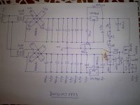
Hola a todos!. Soy nuevo en el foro. Soy de Argentina. Vivo en Marcos Juárez, provincia de Córdoba. Quiero compartir con ustedes un diseño de circuito de mi propiedad que consiste en un power follower (drain común) capáz de desarrollar hasta 1,25W rms (por canal) sobre una carga de 6 ohmios mínimo y con niveles de distorsión más que aceptables. Dispongo de toda su especificación técnica para quien lo desée armar.
Actualmente lo utilizo conectado a la salida de un CD player (2V rms), con lo que obtengo potencias de hasta 0,66W rms sobre 6 ohmios.
Saludos
PD: excuse me for my english!!!
translated by moderation

Hi everyone!. I am new to the forum. I'm from Argentina. I live in Marcos Juárez, Córdoba province. I want to share a circuit design of mine which is a power follower (common drain) capable of developing up to 1.25 W rms (per channel) with a load of 6 ohms minimum and more than acceptable distortion levels. I have all the technical specifications for those who wish to build it.
Currently I use it connected to the output of a CD player (2V rms), with which I get power of 0.66 W rms at 6 ohms.
Greetings
Actualmente lo utilizo conectado a la salida de un CD player (2V rms), con lo que obtengo potencias de hasta 0,66W rms sobre 6 ohmios.
Saludos
PD: excuse me for my english!!!
translated by moderation
Hi everyone!. I am new to the forum. I'm from Argentina. I live in Marcos Juárez, Córdoba province. I want to share a circuit design of mine which is a power follower (common drain) capable of developing up to 1.25 W rms (per channel) with a load of 6 ohms minimum and more than acceptable distortion levels. I have all the technical specifications for those who wish to build it.
Currently I use it connected to the output of a CD player (2V rms), with which I get power of 0.66 W rms at 6 ohms.
Greetings
Attachments
Last edited by a moderator:
Thank you Andrew.
I also want to measure (maybe next week) for reference an NE5532 and a TL072 in the same proto board. I susepct (and hope) the 5532 will also measure well - maybe 10-15ppm, and TL072 at maybe 20-30ppm.
My 'high end' pre-amp I am working on at the moment uses LME4900 buffers (cost a fortune . . . ). Next time round, I'll go for this buffer - less expensive, class A and performanc is not bad.
For a h/phone amp, if you use a dual op-amp, the unused part can be used to do a 2x or 3x amp to feed the buffer stage, since coming straight out of a pre-amp line stage (c. 1V RMS) you need a bit of extra gain I've found. To keep the whole thing class A, you will need to preload the first amplifer stage as well. I might draw something and put it up in the next few days - very busy at the moment.
I'd be interested to hear about your results.
my newest headphones are 95dB/mW
2.2Vac from a CDP will give ~120dB at the ear hole.
I doubt I'll need any extra gain. I suspect I'll be in attenuation mode !
But yes, to the idea. A switchable X1 (+0db), X2 (+6dB), X4 (+12dB) gain setting would be ideal. The difficult part may be adjusting the compensation so that each gain option operates as stabily as the best.
I was going to ask:
1.) would converting the lower 139 to a complementary and becoming a push pull ClassA reduce the performance?
2.) would using the dual soic8 as a two channel single ended ClassA output stage cause overheating? Rth j-a = 145C/W
I'm thinking to reduce the opamp bias slightly from 5mA to 4mA and reduce the voltage from 34Vdc to 24Vdc (this reduces opamp temperature by ~22Cdegrees)
24Vdc still gives ~+11dB of overhead above maximum signal.
Last edited:
Interesting points Andrew
1. No I don't think this will reduce the performance. I basically did this design because good performance can be obtained with a very simple circuit. I think a complimentary class A should work very well, but it will probably be more complex due to the bias requirements. The loaded follower aproach used in this design is simple and very stable.
2. No, I if I understand you correctly, this should work quite well. Likewise, my constant current load on the op-amp outputs is probably a little heavy handed - I think 3mA will also work fine.
Re the point about the gain, the reason I propose this is that if you apply 2x to 3x gain to the headphone stage, I find the volume pot will typically sit between a quarter to to about 10past for most listening - so its setting is similar to where you set it when listening over the speakers.
That said, 3V pk into 32 Ohm headphones is incredibly loud - there's plenty of headroom if you listen at normal levels.
Hi Rob - thanks.
I use . . . . Microsoft Word - nothing special. I am using MS Office and in my version there are some document templates or themses - I just selected one of them and stuck with it.
I'm busy working on a class A headphone amp based on the above BTW. Shown be able to publish something in a week or two.
- Status
- This old topic is closed. If you want to reopen this topic, contact a moderator using the "Report Post" button.
- Home
- Source & Line
- Analog Line Level
- class A Line level buffer