?
I'm not quite sure what you mean by "shelving" Filters are either high pass, low pass, band pass or band reject.
http://www.diyaudio.com/forums/multi-way/22581-passive-line-level-low-high-pass-filter-help.html
Just a Quick one;
I'm looking for information (or a calculator) on how to design/ calculate a 2nd Order shelving High pass filter.
Anny ideas/ links anyone?
I'm not quite sure what you mean by "shelving" Filters are either high pass, low pass, band pass or band reject.
http://www.diyaudio.com/forums/multi-way/22581-passive-line-level-low-high-pass-filter-help.html
Ah,
I was actually of the impression that shelving filters were a distinct type of filters, but what I'm referring to is perhaps only a variation of one of the types you mention?
I did build a filter stage described as a shelving high-pass described on The linkwitz-lab web page.
Active Filters
For this circuit, one could choose a start frequency, and filter gain. As the filter is 1st order, magnitude will rise with 6dB/ oct up to the set gain, and then flatten out, not continue the slope as with a "ordinary" high-pass filter.
The problem is that the slope I get with this filter is not steep enough, so I'm looking for a similar filter but with 12/dB oct slope in stead of only 6.
Does this make any more sense??
Last edited:
OK, I understand now.
Maybe you could email Mr. Linkwitz and he could help you or suggest something.
Maybe you could email Mr. Linkwitz and he could help you or suggest something.
Ah,
I was actually of the impression that shelving filters were a distinct type of filters, but what I'm referring to is perhaps only a variation of one of the types you mention?
I did build a filter stage described as a shelving high-pass described on The linkwitz-lab web page.
Active Filters
For this circuit, one could choose a start frequency, and filter gain. As the filter is 1st order, magnitude will rise with 6dB/ oct up to the set gain, and then flatten out, not continue the slope as with a "ordinary" high-pass filter.
The problem is that the slope I get with this filter is not steep enough, so I'm looking for a similar filter but with 12/dB oct slope in stead of only 6.
Does this make any more sense??
You think so?
I sort of have the feeling that it is a bit below a person of Mr Linkwitz position to answer simple/ stupid questions like that.. The answer is probably right there in some theory or textbook, but being a mere amateur, I'm not the best at translating analogue theory to working circuits...
I sort of have the feeling that it is a bit below a person of Mr Linkwitz position to answer simple/ stupid questions like that.. The answer is probably right there in some theory or textbook, but being a mere amateur, I'm not the best at translating analogue theory to working circuits...
Last edited:
You think so?
I sort of have the feeling that it is a bit below a person of Mr Linkwitz position to answer simple/ stupid questions like that.. The answer is probably right there in some theory or textbook, but being a mere amateur, I'm not the best at translating analogue theory to working circuits...
I still would ask, not expecting him to do all the math for you, but he may know a source or an online link.
I've actually met and talked with Mr. Linkwitz on two separate occasions. I even called him "Siggy." He came to attended our DIYs here in Northern California and demonstrated his loudspeakers for us. He was pleasant to talk to, not all self important or anything like that. A very nice gentleman, so don't worry about it.
Last edited:
It's on his website linkwitzlab.com...look under ordering information for Orion DIY. As noted above SL is very down-to-earth & approachable. Before you ask search his website (which is very extensive) as the answer is likely to be there already. If you don't find it then e-mail him & state your question clearly and succinctly.
I'm not quite sure what you mean by "shelving" Filters are either high pass, low pass, band pass or band reject.
http://www.diyaudio.com/forums/multi-way/22581-passive-line-level-low-high-pass-filter-help.html
There are infinitely many kinds of filters.
I think (not sure, just think) "shelving filter" sometimes refers to high-Q filters. That is my interpretation "shelving filter" from a "digital filter cookbook" article that I read. For example, the typical bass boost function in a subwoofer amp is a second order high pass filter with a big Q, which gives it a bump near the nominal boosted frequency. The nominal bass-boost in decibels is equal to 20*log10(Q).
A "shelving filter" may also refer to a filter such as is used for baffle step correction or "loudness" compensation, where frequencies above a "knee" frequency are attenuated relative to those lower than the "knee" frequency. Alternately, lower frequencies might be attenuated, for example to compensate for effect of a constant directivity horn. That is the way Linkwitz uses the term.
Last edited:
A biquad (AKA Linkwitz transform) can also be used as a second order high shelf. http://www.linkwitzlab.com/images/graphics/f0Q0fpQp.gif
You can also string two first order filters together with a bit less flexibility.
You can also string two first order filters together with a bit less flexibility.
Thank you Bob!
Well, that shows the limitations of my knowledge, I looked at the linkwitz transform and failed to realize it could be made to work as a high-shelf filter! I'll have a closer look at tis, that's for sure!
And if to 6db/ct shelving filters in series adds up to a 12 dB filter, then that is allso an option!
For the biquad, you just plug the numbers into the formulae on the linked page. Gain is negative in the high pass. It is the V/V number so if you need a 6 dB shelf, gain is -2, etc. Gain (v/v) = antilog (gain dB/20). Q can be anything that gets the response shape you want. Use .7 for a the flattest transition, a bit higher if you need a dip/peak at the corners.
Just curious, what is the application?
Just curious, what is the application?
Must admit I'm struggling a bit to figure out what values to put in where in that calculator, obviously, some of the input is intended to be obtained from a woofer measurement..
This circuit do however look very nice as I could need a peak to straighten out a certain notch in my frequency response..
as for the application:
I'm doing a 3-way active set up with a 15" sub and a small two way for each stereo channel.
The two-way uses a SEAS W17cy 6,5" inch midbass, and the tweeter is a SEAS dome with a special "DXT" waveguide/ lens.
THE ART OF SOUND PERFECTION BY SEAS - H1499-06 27TBCD/GB-DXT
This gives a response drop at the top end that I need to adjust.
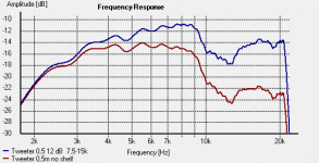
When I measure the tweeter in my application, I get an even more pronounced drop than in the seas-plot, and there is allso a marked dip centered at 13k.
Enclosed is a plot showing the tweeter response without shelving filter in red and with 12/db oct with a F1 of 7,5kHz and 12 db Gain.
This circuit do however look very nice as I could need a peak to straighten out a certain notch in my frequency response..
as for the application:
I'm doing a 3-way active set up with a 15" sub and a small two way for each stereo channel.
The two-way uses a SEAS W17cy 6,5" inch midbass, and the tweeter is a SEAS dome with a special "DXT" waveguide/ lens.
THE ART OF SOUND PERFECTION BY SEAS - H1499-06 27TBCD/GB-DXT
This gives a response drop at the top end that I need to adjust.
When I measure the tweeter in my application, I get an even more pronounced drop than in the seas-plot, and there is allso a marked dip centered at 13k.
Enclosed is a plot showing the tweeter response without shelving filter in red and with 12/db oct with a F1 of 7,5kHz and 12 db Gain.
Attachments
Last edited:
Turned out putting two of those 1st order shelving filters in series to get a 12 db*oct response worked quite well!
Just as well as I just couldn't figure out how to use that bi-quad filter to the same purpose..
Thank's a lot for the advice!!
IN general, this approach only "sort of" works. It's the same problem as trying to cascade two first order RC filter sections to get a second order section - you can only get very low Q values. This might be OK for your application, it depends on what you need in terms of frequency shaping.
A second order shelving filter has two corner frequencies and two Qs, and a biquadratic filter is the only way I know of implementing such a response. The Linkwitz Transform circuit is one way to create a biquadratic filter response, although there are some limitations to the responses that it can create that are inherent in that particular circuit implementation of the biquad.
-Charlie
Charlie,
Thanks for your reply.
I guess you are quite right that two 1st order filters in series only sort of works.. As you can see from the plot I've added in my previous post, the filter didn't exactly target the response problem very accurately.. I can probably optimize a bit by tweeking gain and F1 frequency. I assume I can get the 15-20kHz region up to the same level as 9Khz and down, but I realize I will not get rid of that 13Khz Dip...
Considering the frequency area affected, it might still sound OK.. ?
Obviously, your understanding of active filters are much better than mine.. If you look at the frequency plot, do you see a good way to attack this??
PS.
Both plots are with a 24 dB oct 2,5kHz high pass filter.
Last edited:
Rather than boost the top end, try starting your your high pass with a 1st order roll off up in the waveguide boosted region the way Zaph did in his waveguide TMM. Zaph|Audio
The driver Q to plug into the equations is what you estimate from the shape of the curve you are trying to compensate for.
The driver Q to plug into the equations is what you estimate from the shape of the curve you are trying to compensate for.
A good idea Bob!
Actually, I allready tried to add a 1st order high pass for that purpose.
The result was not that good, and it created a real mess of the x-over between woofer and tweeter.
The SEAS IDUNN kit THE ART OF SOUND PERFECTION BY SEAS - Idunn uses the slope of the passive filter to flatten the response, evidently to very good effect.
I guess that by emulating the x-over of the Idunn actively, I could get simmilar resutls. However, that would mean I'd have to scrap the whole 24db/ oct x-over section which, the high frequency issue appart, works very well.
Regarding the filter calculator, would that value go in to Qp? and what sort of Q would represent the slope I get on my plot??
Must admit I'm struggling a bit to figure out what values to put in where in that calculator, obviously, some of the input is intended to be obtained from a woofer measurement...
I think I can help here... but first: can you tell us more about the speaker and the measurements?
This looks not at all what I would expect from the DXT tweeter. For instance, here is some measurements from someone I know:
Mark K's DXT measurements
What are the dimensions of the cabinet and where is the tweeter mounted? How wide is the baffle there? Is the tweeter not mounted for these measurements? Are there any edges or lips that could be causing a reflection back in to the tweeter horn? Are you using a calibrated microphone to take your measurements?
The DXT tweeter does have a some droop above 10k, but not the response that you show, for sure. I am suspecting that there are other issues that might be solved before you try and throw a biquad at it.
If you do want to figure out how to implement the LT biquad to "fix" the response irregularities, you should read this web page and then download this Excel spreadsheet from TrueAudio:
http://www.trueaudio.com/downloads/linkxfrm.xls
This spreadsheet is designed to show the LT circuit response for a subwoofer, although the calculations are still valid for higher frequencies. To make the response show up and be for higher frequencies, do the following:
Open the spreadsheet
Click on the TABLE tab
In cell A8, enter 100
Click on the Linkwitz Transform Calculator tab
double click on the x-axis scale markings to open up the axis dialog box
enter 1000 for minimum and 100,000 for maximum (it has to be powers of 10)
click OK to close the dialog box
enter the value 0.001 in cell C19 for the capacitor (0.001uF or 1nF)
now enter the following parameters:
Q(0): 1.0
F(0): 8000
Q(p): 1.4
F(p): 13000
I just guesstimated these values from your measurement plot. You should see the result in the plot now. You can also see the component values that you will need if you want to build this circuit. This is the sort of response that the biquad can give you to compensate for the dip that you are measuring. NOTE that the LT biquad can not be realized with this circuit if the parameter "k" is less than zero (k can be found in cell C15 on the first tab).
Let us know and hopefully we will discover the root of the problem.
Charlie
Last edited:
Charlie,
Once again, thanks for your answer.
I certainly agree with you that my plot looks a bit strange, both compared to Mark's measurement and the SEAS data sheet.
Unless something is wrong somewhere, the only explanation I can think of, is that there are some sort of baffle-interaction going on here.
If I do nearfield on the tweeter, the measurement looks different and more as expected, allso taing in to account that the full efect of the DXT lens does not in fluence nearfield.
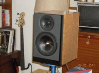
To answer your questions, The baffle is 22 x 35 cm and the center of the tweeter is 6 cm from the top. From the picture attached, you can see qhat it looks like on the baffle, I have glued a 12mm thick sheet of "Armaflex" HVAC Isulation foam which allows the drivers to be counter-sunk without routing.
I have buildt a measurement mic based on the Panasonic MA61 capsule as per description found at Linkwitzlab.com
I run Holm Impulse and I actually got a calibration file for the MA61. This is a generic calibration file, not a unique calibration for my mic in particular.
And thanks a lot for the link to that calculator spreadsheet and the suggested input values, I look forward to play around with this!
If it turns out that I need to correct for a combination of driver roll-off and cabinet interaction as well, the linkwz transformer looks like the better tool!
I'll of course keep posting with any new findings or solutions!
Once again, thanks for your answer.
I certainly agree with you that my plot looks a bit strange, both compared to Mark's measurement and the SEAS data sheet.
Unless something is wrong somewhere, the only explanation I can think of, is that there are some sort of baffle-interaction going on here.
If I do nearfield on the tweeter, the measurement looks different and more as expected, allso taing in to account that the full efect of the DXT lens does not in fluence nearfield.
To answer your questions, The baffle is 22 x 35 cm and the center of the tweeter is 6 cm from the top. From the picture attached, you can see qhat it looks like on the baffle, I have glued a 12mm thick sheet of "Armaflex" HVAC Isulation foam which allows the drivers to be counter-sunk without routing.
I have buildt a measurement mic based on the Panasonic MA61 capsule as per description found at Linkwitzlab.com
I run Holm Impulse and I actually got a calibration file for the MA61. This is a generic calibration file, not a unique calibration for my mic in particular.
And thanks a lot for the link to that calculator spreadsheet and the suggested input values, I look forward to play around with this!
If it turns out that I need to correct for a combination of driver roll-off and cabinet interaction as well, the linkwz transformer looks like the better tool!
I'll of course keep posting with any new findings or solutions!
Attachments
- Status
- This old topic is closed. If you want to reopen this topic, contact a moderator using the "Report Post" button.
- Home
- Source & Line
- Analog Line Level
- Shelving 2nd order high-pass?