ok - so my parts are on order - hopefully I'll get this device functional the 2nd time around --
for testing the device out of an enclosure, does anyone have any recommendations on how to deal with the ground loop humm?
The kit's pcb has a ground connection point that is intended to connect to chassis - what could I use to temporarily ground the device?
Thanks!
Ted
for testing the device out of an enclosure, does anyone have any recommendations on how to deal with the ground loop humm?
The kit's pcb has a ground connection point that is intended to connect to chassis - what could I use to temporarily ground the device?
Thanks!
Ted
projet update
ok - I've got the device working - it performs very nicely as is -
I had thought of increasing the size of filter caps, but the DC output is very smooth - so I think I'll leave it as it --
testing the unit, I have figured out how to ground the board and prevent ground loop hum --
So now it's time to build and enclosure - I stopped by a friend's shop and he had a nice enclosure in his salvage pile - it's just the right size, but it's made out of stainless -- so making holes is going to be a bit of a challenge...
question on determining hot side, chassis contact
stuck in enclosure building phase...
hoping to find 100mA 3AG fuses locally...
plan for power cable:
3 prong 110V power cable to interconnect = 2 leads from transformer.... ground lead to shared chassis ground lug....
fuse and switch wired on hot side of transformer (not exactly clear on how to determine this)
3 secondaries: AC+ 0 AC- connections on pcb -- ground pcb to shared chassis ground --
the one connection I'm a little nervous about is the transformer primaries to the interconnect - its fairly close to the chassis -- can the wires make contact with the chassis if they are well insulated/heat shrink wrapped?
problems with ground hmm
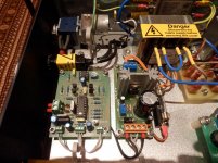
so I found a stainless steel enclosure -
mounted the transformer directly to the bottom of the chassis
used a 3 prong interconnect - ran ground prong to chassis ground
used a grounded toggle power switch - ran ground prong to chassis ground
pcb has a mount for ground connection -- ran that to chassis ground
I'm getting a ground loop hum -
I'm not sure if my transformer it too close to the pcb or if all of the ground connections are interacting with one another --
Will try removing the ground connections from the interconnect and the power switch....
When I remove the pcb from the enclosure and set it further away from the power transformer I don't get hummmmmm......
hmmmm......
project update
ok - good news -
my ground loop issue was due to a bad ground connection -
I redid the ground connection shared by the pcb and the 3 prong IC and everyone is getting along now -
I've been using the device and it is operating normally --
I'm contemplating increasing the size of the caps in the filter - but I don't think this would improve sound quality...
Hoping to button up the enclosure tonight - just some minor cosmetic issues to finalize --
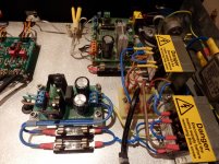
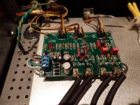
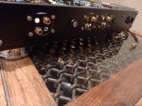
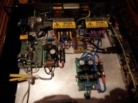
pictures of finished project!
Velleman pre amp kit K8084 - Google Photos
one possible issue: the hot mains wires are enclosed with shrink tubing - but are they too close to the side of the enclosure?
Velleman pre amp kit K8084 - Google Photos
one possible issue: the hot mains wires are enclosed with shrink tubing - but are they too close to the side of the enclosure?
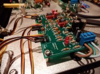
Hello some pictures of mine
works a treat also added volume remote control .. very pleased with the sound, no hum etc very silent
works a treat also added volume remote control .. very pleased with the sound, no hum etc very silent
Attachments


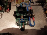
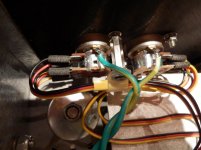
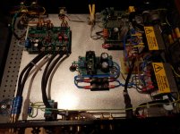
Thanks for the pictures! definitely worth 1K words! Now I have some great ideas for my next project - I wasn't sure how to move the pots and rca inputs off the board -- now it all makes sense --
I see the correct way to rise the pcb off the chassis as well with the metal risers -
Thanks!
T
I see the correct way to rise the pcb off the chassis as well with the metal risers -
Thanks!
T
Thanks for the pictures! definitely worth 1K words! Now I have some great ideas for my next project - I wasn't sure how to move the pots and rca inputs off the board -- now it all makes sense --
I see the correct way to rise the pcb off the chassis as well with the metal risers -
Thanks!
T
Hello
This was my 1st build with the tone control preamp .. I used a extra external power supply (+/- 15v) and fed the preamp PSU as this regulates down to 9v on the PCB.
Next time I would use screened cable, although in the current layout there is no issues .. also make sure you earth the pots
regards
Last edited:
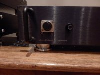
Can you post a close up picture of your op amps jamesfeline?
Thanks
Hello
The op amps I used :
Bur Brown OPA2134PA
- Status
- This old topic is closed. If you want to reopen this topic, contact a moderator using the "Report Post" button.
- Home
- Source & Line
- Analog Line Level
- Velleman K8084 pre-amp kit question