Hi,
Some time ago I built a tube amp for my electric guitar that sounds too mid-rangey. After fiddling around with a graphic eq I have found that I want a -3 db dip at 800 Hz, with a 1.5 db/oct slope (-1.5 db @ 400 Hz, -3 db @ 800 Hz, -1.5 db @ 1600 Hz).
I want to build this into a very simple tube amplifier, so I think I want a passive filter between the two pre-amp stages. From what I have been able to gather, a lo-pass and hi-pass filter (both with cutoff @ 800 Hz) in parallell should do the trick and I tried building such a constellation (with idential R- and C-values for the filters), but this resulted in a massive volume loss and generally didn't sound good. I think the volume loss stems from the two resistors in the filters forming a potential divider, leaving only 50% of the signal for the next preamp-stage, but my electronics skills are very basic, so this is probably not the complete picture.
Any ideas how such a circuit could be constructed? Would it help if I used a low value resistor in the lo-pass filter and a high value resistor in the hi-pass filter, and adjusted the capacitor values accordingly, to remedy the volume loss?
I'd be most grateful if someone would point me in the direction of some newbie friendly band-stop filter literature.
Thanks!
Hi oddbjorn,
If I understand you correctly you might just "google" the term "notch filters". I think that would be useful. It doesn't have to be low level. Any decent site that explains highlevel speaker cross-overs will usually throw in a notch filter circuit. There will often be two types, parrallel and series and a bipolar cap and appropriate inductor with a potentiometer will give you a nice notch with variable depth controlled by the pot....
I know I haven't answered your question (I've noticed that people seldom do!) but the high level approach avoids impedence matching etc....
They will explain the formula for the centre fequency etc.
Good luck, Jonathan
Last edited:
Jonathan,
Thanks for taking the time to answer, I really appreciate it.
An adjustable resistance "series LC circuit" in parallell with my second pre-amp stage looks like exacly what I'm after! Using the the formulas I've found, a 10mH inductor and a 3.3µF capacitor should give a center frequency of 876.56Hz. Close enough to what I was looking for. Getting components at these values with 5% tolerance seems easy enough.
I'll let you know how it works out!
I am not exactly sure about the values. What I had in mind was a high level network between the speaker and power amp. The values you indicated look okay for that.........The low level small signal values may be different if it goes between pre-amp stages because the impedences are a lot higher.
The network you want is also called a "presence" or mid-range tone control.
The network you want is also called a "presence" or mid-range tone control.
Last edited:
Hello again!
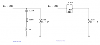
I've now tried constructing both a series LC filter and a parallell LC filter using the component values 10mH and 3.3µF, but I'm clearly doing something wrong, as I can not hear any audible difference with the filter connected vs. bypassed. Please see the attached schematics. Do they look alright to you?
Or could it possibly be that this filters Q value is too high, so that even though the filter is working it's not audible to my ears? If so, how can I make the band stop region wider so that the filter starts rolling off at 400 Hz, goes down to -3db to -5db at 800 Hz and back up to 0db at 1600 Hz?
Attachments
Aha! So the impedance of this circuit is very low for the full frequency range, causing it to "steal" the whole signal instead of just the resonant frequency?
It seems the circuit I'm trying to create goes under the name Varitone circuit and was first seen in Gibson semi-acoustics from the 60s. The Varitone circuit uses a large inductor, as you suggested, and a switchable set of capacitors.
I have ordered two Fasel Wah-inductors (approx. 500mH each and ridiculously expensive, but easy to find) to experiment with. I'll keep you posted on how it works out!")
It seems the circuit I'm trying to create goes under the name Varitone circuit and was first seen in Gibson semi-acoustics from the 60s. The Varitone circuit uses a large inductor, as you suggested, and a switchable set of capacitors.
I have ordered two Fasel Wah-inductors (approx. 500mH each and ridiculously expensive, but easy to find) to experiment with. I'll keep you posted on how it works out!
No, the circuit does not "steal" anything, or at least not enough for anyone to notice. At the resonant frequency the reactance of each component is about 50 ohms. Assuming a Q of 100 (wild guess, but probably within a factor of 2 of the truth) this means that the total impedance is 5K. 5k versus 1M means that you lose 0.5% of the signal. I don't think you will notice that.

- Status
- This old topic is closed. If you want to reopen this topic, contact a moderator using the "Report Post" button.
- Home
- Source & Line
- Analog Line Level
- Ideas for a simple passive band-stop filter?