I've been after a variable frequency shelving filter to use in my preamplifier for a while and I've come to the following iteration.
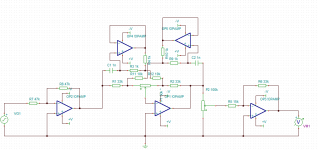
I realise it could be a bit messy to look at, so the basic topologic explanation is as follows:
The first and last opamp are only buffers, the actual tilt filter is our centre opamp of this image.
The tilt filter is the same topologically as the quad preamplifier filter that is found all over the net, with only one difference. There are two capacitance multipliers inserted as the frequency setting capacitors.
People who have fiddled with the original circuit will know that changing the resistances in the original topology has effects on the symmetry of the shelving effect.
This method enables filter centre frequency to be set by resistances and also continuously (I entertained the possibility of a switched ladder, but it wasn't any less component wise and slightly less flexible). I intend to set the frequency remotely through a set of H11F optocouplers. Based on the analysis the voltage across the setting resistors is small enough for the H11F couplers to work in its uncompressed resistive region.
I've noticed that the capacitance multiplier examples always ground the cap, but I don't see why it can't be floating. Am I missing some bandwidth and phase issues here?
Attachments
Hi - Not such a bad idea, really.
I have some Rotel gear that revisits the Quad tilt tone control system. In modern domestic systems the effect is quite satisfactory, even though it is only switched between low. +/- 0, 1 & 3dB slopes (from memory). Any requirement really depends on whether you are trying to compensate for minor overall tonal balance errors or you like playing with strong effects.
Adding shelving seems like a sensible move for any control steeper than 3dB/octave and though I don't recall from JLH's descriptions that Quad controls were shelved, the absence of discontinuity at the centre frequency really is an improvement over typical commercial Baxandall control implementations.
Perhaps you would like to comment further on this, and what range of slope and centre frequency you are aiming for in the circuit operation. Perhaps others will also add something when there are a few more specifics to consider.
Thanks for your interest, I breadboarded this and the circuit seems to function as expected.
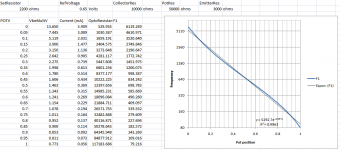
I was aiming for a target of 100Hz to 10k centre frequency adjustment, though with the values shown it's about 120Hz at 50k (in the multipliers) up to 5.1kHz at 330ohms (minimum resistance of a H11F2)
Pivoting variation is up to 16dB (+-8dB), which is about what I want. 12dB target, 20dB maximum. The absolute variation can obviously be varied by changing the values of the gain setting resistors around it. I still need to put in place a pivot defeat.
However I realised one flaw in my logic of getting stable pivoting volume - it's that the overall volume when pivoting doesn't actually remain constant at more extreme frequencies, but the volume near the centre frequency does. That said I've arrived at the conclusion that it won't be much of an issue in use, esp. compared with the limitations of the standard baxandall tone implementations.
I figure for even more flexibility one could place two of these stages in series, which allows for creation of a band filter if required.
I'm working on the design of the actual current and pot control now though. I've managed to model the optocoupler linearity with an equation that quite closely matches the datasheet, but the adjustment linearity is some strange power relation. Nevertheless, I've arrived at a method of generating the reference current from a linear potentiometer which I am reasonably happy about. It moves the frequency very approximately up and down by octaves.
Of particular concern here though is that the lowest control current (currently approx 80Hz) is only 56uA, which I'm not sure if simple circuitry will be able to maintain (keeping in mind that this signal needs to be mirrored to four individual couplers, each with their individual tolerances)
I might need to sacrifice the dynamic range for practicality, but hopefully not.
Attachments
- Status
- This old topic is closed. If you want to reopen this topic, contact a moderator using the "Report Post" button.