For my little brother (he is literally quite small ") ), I'm currently working on a subwoofer. Because he has some specific wishes, I'm making the filter myself. Before I start on the schematics, I would love your input on the block diagram. I'm for instance still contemplating if the relais is in the right spot; I can also but the input buffer for the L+R signal after the summing circuit and put the relais before the input buffers.
), I'm currently working on a subwoofer. Because he has some specific wishes, I'm making the filter myself. Before I start on the schematics, I would love your input on the block diagram. I'm for instance still contemplating if the relais is in the right spot; I can also but the input buffer for the L+R signal after the summing circuit and put the relais before the input buffers.

-Black arrows are signal, blue are control
-Speaker level inputs (L+R)
-Line level inputs (L+R)
-Summing circuit is an inverting opamp summing
-An automatic switch which senses if there is an LFE signal and with no signal present holds the relais for a certain amount of time (few minutes), relais can be released by pressing button
Cheers Maarten
), I'm currently working on a subwoofer. Because he has some specific wishes, I'm making the filter myself. Before I start on the schematics, I would love your input on the block diagram. I'm for instance still contemplating if the relais is in the right spot; I can also but the input buffer for the L+R signal after the summing circuit and put the relais before the input buffers.
-Black arrows are signal, blue are control
-Speaker level inputs (L+R)
-Line level inputs (L+R)
-Summing circuit is an inverting opamp summing
-An automatic switch which senses if there is an LFE signal and with no signal present holds the relais for a certain amount of time (few minutes), relais can be released by pressing button
Cheers Maarten
Very similar to something I built for somebody a few years ago, but I chose to let the LFE signal run to all intents and purposes unfiltered as by it's nature it should be the correct bandwidth anyway. Then I just put the LFE/stereo select switch/relay before the EQ (using your diagram).
If that takes a bit of getting your head around, there is a block diagram for it on my website in the Bespoke section.
If that takes a bit of getting your head around, there is a block diagram for it on my website in the Bespoke section.
Last edited:
Thanks for the input Richie. That was also the plan to skip the LR filter for the LFE, but seeing my diagram again I see it's not correct (not having the most 'awake' day, as my mondays tend to be ).
The LR low pass should be directly after the summing block.
Thank you for pointing this out.
).The LR low pass should be directly after the summing block.
Thank you for pointing this out.
Finally finished the schematic. This is my first somewhat more elaborate putting together of building blocks. The different blocks I got from different desings / places.
Pleas ignore IC9B (not used right now) and the 2nd switch of the relais.
Still had some questions for you kind experts, if your willing to answer them:
-Are C204, C212, C222, necessary?
-Is the volume pot (VR3) in the correct place? (Before the output buffer)
-Is this the rorrect way to hook up VR3 or should I make a voltage divider (pot in series and a resistor to ground)?
-Is this the correct way to build a 0-180 phase control (are these the correct values for this frequency range)?
-Any other input and advice is welcome of course..
The schematic:

Thank you,
Cheers Maarten
Pleas ignore IC9B (not used right now) and the 2nd switch of the relais.
Still had some questions for you kind experts, if your willing to answer them:
-Are C204, C212, C222, necessary?
-Is the volume pot (VR3) in the correct place? (Before the output buffer)
-Is this the rorrect way to hook up VR3 or should I make a voltage divider (pot in series and a resistor to ground)?
-Is this the correct way to build a 0-180 phase control (are these the correct values for this frequency range)?
-Any other input and advice is welcome of course..
The schematic:
Thank you,
Cheers Maarten
1. No the caps are not needed.
2. VR3 is OK there but consider your max input level.
3. You can make a volume control that way but it's OK as you have it.
4. I think you have it almost correct, omit the feedback cap. As for values I suggest you simulate.
The jumpers across the tone controls will cause problems when you short the op-amps out.
Thanks again for taking the time too look at it Richie.
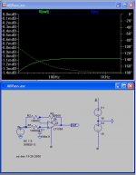
I modelled the phase control in LTSpice. This is the first time I used a modelling program, so I'm not sure I did it correct. But from my modelling it seems that in the frequency range of interest (20-80 Hz), a 220nF cap with a 100Kohm pot gives the best trade-off between amount of phase-shift and phase differences over the frequency range.
220nF with pot at 10kOhm:

220nF with pot at 100kOhm:

100nF with pot at 10kOhm:

100nF with pot at 100kOhm
I modelled the phase control in LTSpice. This is the first time I used a modelling program, so I'm not sure I did it correct. But from my modelling it seems that in the frequency range of interest (20-80 Hz), a 220nF cap with a 100Kohm pot gives the best trade-off between amount of phase-shift and phase differences over the frequency range.
220nF with pot at 10kOhm:
220nF with pot at 100kOhm:
100nF with pot at 10kOhm:
100nF with pot at 100kOhm
Attachments
- Status
- This old topic is closed. If you want to reopen this topic, contact a moderator using the "Report Post" button.