I just purchased a CS3310-based preamp/source select/volume control on eBay to play around with after having read a little about alternative attenuators (an LDR based attenuator is on my DIY to-do list too). It's similar to this: Crystal c3310 Volume remote control preamplifier kit - eBay (item 190434511073 end time Sep-21-10 19:46:08 PDT)
Sadly it appears from the data sheet that there is no way to bypass the internal op-amp in order to use only tubes for the gain portion. Is that true? If so, perhaps a tube buffer after the pre would be of value here? What do you think? I know nothing about such internal op-amps and for that reason would prefer the option of bypassing with something I know (even if it's an opamp).
If it can be bypassed, anyone care to help me understand how?
Thanks,
Carl
hi!
I just got mine in the mail today but no sheet would you send me one PLEASE!
Or post it here the question I have is I see 6-0-6 and says power on the display board,and I see outputs one and two but not three marking on the board so I am a little confused ,Need a diagram and I'll be set!
Thanks,
NoSmoking
I'll check in the next few days, but I can say the 6-0-6 is for the 6v inputs. Designed for a 12v AC input with a center tap. I took a Rat Shack 12.6v filament transformer and wired one leg to each of the 6 inputs, then the center tap to the 0 input. That works fine. Not sure what you mean about the outputs and not having three. This unit (mine anyway) is just for stereo. Haven't tested the power out from the display but was hoping it would be 12v or less that I could use as a trigger for my amp.
As for any instructions, I got none with mine, but looked up the datasheet for the CS3310, which you can easily get online (Google cs3310). Moved on to some other projects temporarily but will probably get back to playing with mine in a bit.
Carl
As for any instructions, I got none with mine, but looked up the datasheet for the CS3310, which you can easily get online (Google cs3310). Moved on to some other projects temporarily but will probably get back to playing with mine in a bit.
Carl
Hi guys I built one of these around a year ago and I have a copy of the instruction guide the seller provided (not the same as the one above) when I emailed him. If you'd like a copy PM me your email and I'll be happy to forward it along with some other correspondence I had with the seller about other questions I had.
Luke
Luke
Thanks, Luke. You've got a PM. I looked at mine tonight and it has a plastic 3-wire jack for outputs. Silk screening is a bit tough to read, but center is ground and the two side pins are for l and r channels. On some listings I have seen these outputs labeled as preamp inputs, but the inputs for this device are RCA jacks on the back. These 3 pins are for output to the next stage (buffer, amp, or, I suppose, another "preamp").
Last edited:
Email just sent.
Here is a link to the thread I made at the time http://www.diyaudio.com/forums/anal...rst-ever-diyish-preamp-remote-volume-etc.html
I get Turn-off pop which I could make a circuit to prevent but I just turn off my amp first.
Luke
Here is a link to the thread I made at the time http://www.diyaudio.com/forums/anal...rst-ever-diyish-preamp-remote-volume-etc.html
I get Turn-off pop which I could make a circuit to prevent but I just turn off my amp first.
Luke
you are free to download the source for arduino controllers and adapt it to the pga board. there is pga code already in the volu-master code base. see www.amb.org/audio/lcduino and the software download link for the zipfile. you need to use arduino (free devel software) instead of their controller. but where their controller touches the pga (chipsel, clock, data; the spi pins) you use the lcduino and its code, instead.
you can then change all the strings to spanish inside the arduino ide, rebuild the hex and download it. but again, its only for aduino (328) chips, so you would have to stop using the ebay lcd controller part and use only the pga board part.
you can then change all the strings to spanish inside the arduino ide, rebuild the hex and download it. but again, its only for aduino (328) chips, so you would have to stop using the ebay lcd controller part and use only the pga board part.
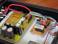
pic of a 3-PGA ebay board that I used for 1 chip, in this build.
a small glue board was made (i2c port expander) so that my controller would be able to big-bang the needed SPI for the pga chip, but use i2c for it. it was just that chip and some wiring to connect the pga 'engine' board with the lcduino controller. the code is already in place in the v1.0 base for pga-over-i2c.
a small glue board was made (i2c port expander) so that my controller would be able to big-bang the needed SPI for the pga chip, but use i2c for it. it was just that chip and some wiring to connect the pga 'engine' board with the lcduino controller. the code is already in place in the v1.0 base for pga-over-i2c.
Attachments
- Status
- This old topic is closed. If you want to reopen this topic, contact a moderator using the "Report Post" button.
- Home
- Source & Line
- Analog Line Level
- CS3310 remote volume and source select