Hi All,
I hope somebody can help me with the following;
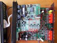
I have a fully operational 5.1 DTS/dolby surround decoder from Teufel, the decoderstation 3, which decodes a digital/optical signal to 6 analog channels
Because of the excessive use of elco's I want to replace some of them with film-capacitors. I have the feeling not all of them are necessary, so I want to remove the one's not necessary.
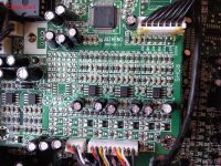
The input-signal is processed by the DAC. After that you see 1 couple capacitor (CC) per channel (photo overwiew.jpg), then the signal is transferred trough the red-striped wire (--> A)
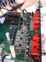
In the third photo (analog_board) there are again 6 CC's and after some sort of processing of the signal (I dont't have a clue what this IC does) there are again 6 CC's. After (what I think is) an extra ampflifier-stage there are again 6 CC's.
I hope some of the last capacitors can be shortened/removed. Furthermore I would like to replace the necessary CC's with film-capacitors.
The value of all of the CC's is 10uF / 50V. I read somewhere that when there is no DC between capacitor-pins measured when in progress, you could replace them with non-polarity capacitors. Is this correct?
I hope someone could help me with this one??
Thanx very much in advance
Maikel
I hope somebody can help me with the following;
I have a fully operational 5.1 DTS/dolby surround decoder from Teufel, the decoderstation 3, which decodes a digital/optical signal to 6 analog channels
Because of the excessive use of elco's I want to replace some of them with film-capacitors. I have the feeling not all of them are necessary, so I want to remove the one's not necessary.
The input-signal is processed by the DAC. After that you see 1 couple capacitor (CC) per channel (photo overwiew.jpg), then the signal is transferred trough the red-striped wire (--> A)
In the third photo (analog_board) there are again 6 CC's and after some sort of processing of the signal (I dont't have a clue what this IC does) there are again 6 CC's. After (what I think is) an extra ampflifier-stage there are again 6 CC's.
I hope some of the last capacitors can be shortened/removed. Furthermore I would like to replace the necessary CC's with film-capacitors.
The value of all of the CC's is 10uF / 50V. I read somewhere that when there is no DC between capacitor-pins measured when in progress, you could replace them with non-polarity capacitors. Is this correct?
I hope someone could help me with this one??
Thanx very much in advance
Maikel
Attachments
Do you have schematics? I'm almost willing to bet that the electrolytic caps you are looking at are actually mostly for decoupling the supply rails. A few of them near the RCA jacks might be audio coupling caps.. Without a better understanding of the design criteria used in their selection I would leave them alone.
Also this stuff is ESD sensitive, I hope you are disassembling in a static free area with the minimum of an ESD wrist-strap. (An ESD mat would be a good idea too.)
Also this stuff is ESD sensitive, I hope you are disassembling in a static free area with the minimum of an ESD wrist-strap. (An ESD mat would be a good idea too.)
Last edited:
Do you have schematics? I'm almost willing to bet that the electrolytic caps you are looking at are actually mostly for decoupling the supply rails. A few of them near the RCA jacks might be audio coupling caps.. Without a better understanding of the design criteria used in their selection I would leave them alone.
Also this stuff is ESD sensitive, I hope you are disassembling in a static free area with the minimum of an ESD wrist-strap. (An ESD mat would be a good idea too.)
Hi Kevinkr, thanks for you're reply. Unfortunately I don't have any schematics.
I didn't knew this is ESD sensitive
 , I didn't touch any component but did'nt use any wrist-strap. Hope nothing is damaged, I'm going to use this now.
I'm going to try to find out if the caps are indeed for decoupling the supply-rail. How can I check/verify this. Is it enough to see if the - of the caps are on gnd of the power-suply-rail??
Could you leed me in the right direction?
I'm going to email teufel, maybe they can send me the schematics, I can't find any on internet
Thanks in advance
Maikel
Hi, New here.
I just got hold of a Teufel decoderstation myself - but the unit alone without remote control or power supply.
I'm hoping to make do without the remote, but the power supply socket on the unit's an unusual XLR marked, "AC input 2x9v ~1A"
Question: can I just get 240V transformer with a 9V winding and wire it in there, or does the original external power supply come with any other circuitry? (A diagram would help byt Teufel Audio say the unit's too old and they no longer have that info)
Any help appreciated,
Steve
You'd need a 2x 9 V xfmr, center-tapped, about 20 VA. No other electronics though.
Also see this thread (in German) for information on the plug - it's a small Tuchel (company now called Amphenol-Tuchel), not an XLR.
Also see this thread (in German) for information on the plug - it's a small Tuchel (company now called Amphenol-Tuchel), not an XLR.
.You'd need a 2x 9 V xfmr, center-tapped, about 20 VA. No other electronics though.
Thanks Sgrossklass,
OK I've got a transformer that'll do it - but is there any way you can draw me a circuit? (I'll just bypass the 3-pin socket, unavailable here, and basically wire via something else to the PCB).
my transformer has 12V 9V and 0V secondary windings on each side.
Transformer:
12V 9V 0V
____|___________?
12V 9V 0V
____|___________?
PCB:
AC AC G
Any further help appreciated!
Basically you should be able to connect the two 0V wires together. Verify that you get about 18 VAC across the two 9V taps, otherwise you may need to invert polarity on one of the windings. (If the windings are out of phase, their inductance cancels out.)
The midpoint then goes to G, the two outer ends to the AC connections.
The midpoint then goes to G, the two outer ends to the AC connections.
- Status
- This old topic is closed. If you want to reopen this topic, contact a moderator using the "Report Post" button.
- Home
- Source & Line
- Analog Line Level
- Replace / remove couple capacitors in Teufel decoderstation 3