I thought I would detail my preamp project. I've had this idea for a while but only recently got around to starting it. Seen a couple of threads previously with similar intentions but looks like they never got finished…
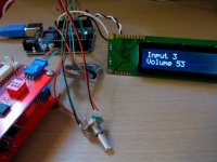
I’m going to use an Arduino for control because I really like open source hardware and its so easy to work with. The Arduino will control a passive, relay-based input selector and Attenuator via I2C using a rotary encoder/buttons/remote. Not sure if I’ll use an LCD display in the final design but I have one at the moment anyway. Not sure about the tube stage yet but I’m thinking a Low Voltage Aikido (Aikido LV)
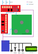
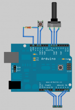
Attached is a diagram showing the general layout.
I’m going to use an Arduino for control because I really like open source hardware and its so easy to work with. The Arduino will control a passive, relay-based input selector and Attenuator via I2C using a rotary encoder/buttons/remote. Not sure if I’ll use an LCD display in the final design but I have one at the moment anyway. Not sure about the tube stage yet but I’m thinking a Low Voltage Aikido (Aikido LV)
Attached is a diagram showing the general layout.
Attachments
I think it's unnecessary complicated with tubes and relay-based Attenuator.You can take an Op-amp and pga2310 instead and it will cost less and make better sound.
I know some people want something extravagant and very expensive, but it sounds not better then "cheap" things.
I know some people want something extravagant and very expensive, but it sounds not better then "cheap" things.
Yeah I was very undecided about using the PGA2310 vs relay attenuator for volume control but decided on the relay attenuator purely because it was more interesting to build.
But I think quite a few people would disagree with you about a PGA2310 and opamp sounding better than tube stage and pot!
But I think quite a few people would disagree with you about a PGA2310 and opamp sounding better than tube stage and pot!
I recomend this here RelaiXed -- Balanced pre-amplifier
if you want something special.
if you want something special.
I recomend this here RelaiXed -- Balanced pre-amplifier
if you want something special.
Yeah I've seen this design, its very good. My attenuator is pretty much the same schematic (also same as the Joshua Tree and Jos van Eijndhoven's work) except mine has double the amount of steps and its not balanced. I don't have any balanced equipment and I've never had any hum or interference so I don't really see the point of it. Mine also uses smaller relays and all SMD parts. I'll post schematics and layout soon!
I recomend this here RelaiXed -- Balanced pre-amplifier
if you want something special.
I tried this, but it has bug, the rotary enoder need to debounce by 1uf capacitor
and the decrement has inconsistant result..
Some of the features are:
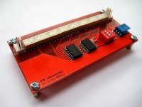
I2C controlled using an MCP23008
The I2C address can be set using small DIP switches
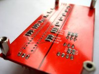
Surface mount components for shortest possible signal path
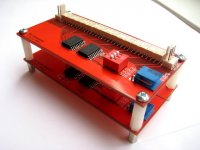
PCBs are small (100 x 50 mm) and stackable
Should work as single ended or balanced (need to one per channel)
Omron G6K relays - High quality, low power, very compact with gold alloy contacts
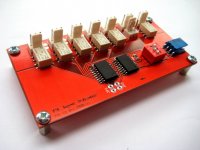
The input selector has 5 inputs and 1 output relay for muting to stop preamp pop or thump etc.
The attenuator has 128 steps + mute.
Here is a pic of the bottom of the attenuator board
I2C controlled using an MCP23008
The I2C address can be set using small DIP switches
Surface mount components for shortest possible signal path
PCBs are small (100 x 50 mm) and stackable
Should work as single ended or balanced (need to one per channel)
Omron G6K relays - High quality, low power, very compact with gold alloy contacts
The input selector has 5 inputs and 1 output relay for muting to stop preamp pop or thump etc.
The attenuator has 128 steps + mute.
Here is a pic of the bottom of the attenuator board
Attachments
I tried this, but it has bug, the rotary enoder need to debounce by 1uf capacitor
and the decrement has inconsistant result..
That's a shame!
I'm working on my arduino code now but so far it just seems so easy! I'll post results soon.
watching with interest. so has both attenuator and selector yes? or this is separate functionality from same board? will you have PCBs? I do not need tube stage, only balanced selector and attenuator, with buffer (I will just use IC or discrete diamond buffer)
A separate board for the attenuator and input selector. Tube stage and control is all separate. I wanted it to be modular so I could change parts later. You could use arduino or PIC or anything that does I2c to control the attenuator and input selector
I already have PCBs! Got quite a few spare (like 8 or so) due to not being able to order low quantities of 1 or 2 from PCB fabricators.
Very nice maxw. I have used a PGA2320 and am very happy with the results. I am using an mbed controller (Rapid Prototyping for Microcontrollers | mbed) to do the control. See my website for some shots and a write-up.
Good luck with your project. Looks very interesting.
Good luck with your project. Looks very interesting.
Not sure about the tube stage yet but I’m thinking a Low Voltage Aikido
Call me old fashioned but i thought a preamp design begins with the actual preamp circuit/ power supply and generally stuff which relates in some way to the sound and not with the cosmetics. Else it may become a micro project with some analogue functionality
")
Any chance you could release the code here?
Thanks
Sure, here is the basic code using a rotary encoder to control the volume and a button to switch sources. I'll share the rest of the code when its finished.
Attachments
Very nice maxw. I have used a PGA2320 and am very happy with the results. I am using an mbed controller (Rapid Prototyping for Microcontrollers | mbed) to do the control. See my website for some shots and a write-up.
Good luck with your project. Looks very interesting.
Thanks Bonsai, I've seen your X-Altra Mini One and really like the design
Call me old fashioned but i thought a preamp design begins with the actual preamp circuit/ power supply and generally stuff which relates in some way to the sound and not with the cosmetics. Else it may become a micro project with some analogue functionality
You are old fashioned
With my current plan I could use the Aikido, a B1, an opamp etc or completely passive and still have remote/input control/attenuation. Basically I want to be able to change it at will but still have these comforts.
Sure, here is the basic code using a rotary encoder to control the volume and a button to switch sources. I'll share the rest of the code when its finished.
Thanks Max this is very cool, I have been playing around with an arduino mega and thanks to linux-works I have got it controlling a pga2310 with the help of this post on the arduino website. So far all I have managed to do is get the pga2310 to run in a loop increasing the volume up and down. I would like to use a pga2310 based attenuator in place of your relay volume control. I will build a relay based attenuator eventually, right now I am on low budget and was given a heap of free pha2310's from a work mate. How would I go about converting your marvelous code to do this?
Thanks Max this is very cool, I have been playing around with an arduino mega and thanks to linux-works I have got it controlling a pga2310 with the help of this post on the arduino website. So far all I have managed to do is get the pga2310 to run in a loop increasing the volume up and down. I would like to use a pga2310 based attenuator in place of your relay volume control. I will build a relay based attenuator eventually, right now I am on low budget and was given a heap of free pha2310's from a work mate. How would I go about converting your marvelous code to do this?
Have you tried combing my relay attenuator code above using an encoder and the code I posted in the arduino forum? This should get you going with an encoder controlling a PGA.
- Home
- Source & Line
- Analog Line Level
- My Preamp Project: Arduino, I2C, relay selector+attenuator, tube stage