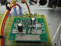
I have been using passive pre-amp in my listening environment. Since the volume pot is 50 kA, it can cause undesirable high-freq roll off for my 498xx based power amp (input 33k//470p). I finally made a unity gain pre-amp (buffer). It is just a quick project where an old spare PCB is used to populate the opamp circuit. The board was designed for signal conditioning with Linear active filter chips. The 50 kA pot is followed by two OPA134 as unit-gain buffers. Additional output RCA sockets are added for driving bi-amp. Regulated +/- 15 V supply is from a separate supply chassis. LM317/337 and some caps form the simple supply. Everything just work great! No noise (hiss and hum) can be heard from the speaker with the pre-amp input grounded.
I will modify it slightly for some gain no greater than 10. I think this is very sufficient for today digital sources.
I will modify it slightly for some gain no greater than 10. I think this is very sufficient for today digital sources.
Attachments
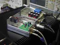
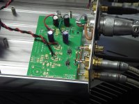
I have been using passive pre-amp in my listening environment. Since the volume pot is 50 kA, it can cause undesirable high-freq roll off for my 498xx based power amp (input 33k//470p). I finally made a unity gain pre-amp (buffer). It is just a quick project where an old spare PCB is used to populate the opamp circuit. The board was designed for signal conditioning with Linear active filter chips. The 50 kA pot is followed by two OPA134 as unit-gain buffers. Additional output RCA sockets are added for driving bi-amp. Regulated +/- 15 V supply is from a separate supply chassis. LM317/337 and some caps form the simple supply. Everything just work great! No noise (hiss and hum) can be heard from the speaker with the pre-amp input grounded.
I will modify it slightly for some gain no greater than 10. I think this is very sufficient for today digital sources.
First of all I would like to congratulate you on a job well done. I especially like the way you isolated the power supply in its own chassis. If you ever get tired of an opamp based unity gain buffer, please look into Salas direct coupled Class A buffer with shunt regulation right here. It is inspired by Nelson Pass' B1 and therefore only uses Jfets. I am building a differential/balanced version of that design.
Kind regards,
Anand.
Thank you Anand!
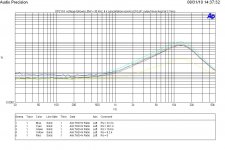
My buffer pre-amp shown in thread #1 is borrowed to a friend for listening evaluation. I use the TI opamp universal test board (fixture) to build another pre-amp. LME49720 is soldered to the board as the first test unit. The chip is still configured as a voltage-follower. A cancellation resistor is inserted between output and -IN. A 50 kA volume pot is followed by the opamp. Hence, the source resistance of the opamp is not a fixed value. A fixed cancellation resistor won't offer maximum cancellation for different pot positions.
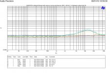
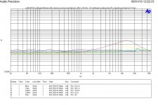
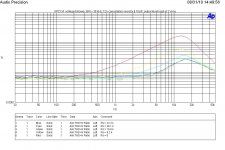
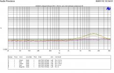
Let see the THD vs freq for cancellation resistor equal to 1 k. The output level was kept at 3 Vrms in order to maintain signal to noise ratio. Output load is the AP input 100 k resistance. The curve for Rs = 0 is essentially the AP's THD vs freq.
Other plot is for cancellation resistor equal to 16 k. We can see that this is over kill! The distortion is worst for Rs = 0. Maximum (lowest distortion) cancellation occurs at Rs = 16.8 k. Well, Rs is nearly identical to the cancellation resistance.
Based on the plots, a 1 k cancellation resistor offers better performance. Taking listening level into account, 16 k is probably the choice. I will try 10 k next.
My buffer pre-amp shown in thread #1 is borrowed to a friend for listening evaluation. I use the TI opamp universal test board (fixture) to build another pre-amp. LME49720 is soldered to the board as the first test unit. The chip is still configured as a voltage-follower. A cancellation resistor is inserted between output and -IN. A 50 kA volume pot is followed by the opamp. Hence, the source resistance of the opamp is not a fixed value. A fixed cancellation resistor won't offer maximum cancellation for different pot positions.
Let see the THD vs freq for cancellation resistor equal to 1 k. The output level was kept at 3 Vrms in order to maintain signal to noise ratio. Output load is the AP input 100 k resistance. The curve for Rs = 0 is essentially the AP's THD vs freq.
Other plot is for cancellation resistor equal to 16 k. We can see that this is over kill! The distortion is worst for Rs = 0. Maximum (lowest distortion) cancellation occurs at Rs = 16.8 k. Well, Rs is nearly identical to the cancellation resistance.
Based on the plots, a 1 k cancellation resistor offers better performance. Taking listening level into account, 16 k is probably the choice. I will try 10 k next.
Attachments
Last edited:
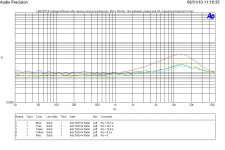
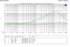
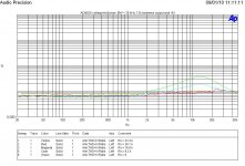
The plot is for a cancellation resistor equal to 12 k. It sees this is a better value compared to the previous 1 k and 16 k. We have maximum (complete?) cancellation for the first three Rs values.
The test fixture is shown as well.
The test fixture is shown as well.
Attachments
Last edited:
Wounderfull result ! what a little resistor can do !
Yes, it seems no need to go for bootstrapping the rails.
The LME series is superb in supressing common mode distortion. I asume your OPA134 version whould show much bigger differences.
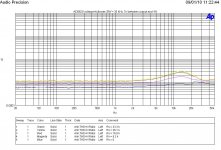
Yes, you are right that the LME outperforms OPA134 in this regard. I tested the OPA2134 for CM distortion. The cancellation resistor is still effective. However, the chip does not like high valued resistor where it oscillates. A 10 pF cap is parallel with the cancellation resistor to stop osc.
The plots for 1 k, 6 k and 12 k cancellation resistor are shown below.
Attachments
is the cancellation resistor a resistance in the normally seen shorting link of the opamp as (non-inverting) unity gain follower?
Normally we see Output connected to -IN as a direct short.
This has come up in a couple of other threads recently.
Andrew
This was done by Silicon Chip magazine in their Studio Series Preamplifier of October 2005 with an OPA2134.(P.29)
SandyK
is the cancellation resistor a resistance in the normally seen shorting link of the opamp as (non-inverting) unity gain follower?
Normally we see Output connected to -IN as a direct short.
This has come up in a couple of other threads recently.
Yes, this is a resistor between output and -IN.
Great ! I think this is the first time somebody does that in public.
Do you ware of the Samuel Groner opamp distortion report? http://www.sg-acoustics.ch/analogue_audio/ic_opamps/pdf/opamp_distortion.pdf
One more test data for CM distortion in voltage follower. The opamp under test is AD8620. Again, 12 k cancellation resistor seems to be a good choice.
Attachments
To necrobump this a bit :
How is the distortion affected by signal level, i e CM voltage, fex if you have a volume pot before the buffer? Here and in Selfs book the testing is done at quite high voltage.
I rarely feed 3Vrms into my power amps, as the distortion from the speakers probably outshine the buffer distortion by a couple of magnitudes then")
How is the distortion affected by signal level, i e CM voltage, fex if you have a volume pot before the buffer? Here and in Selfs book the testing is done at quite high voltage.
I rarely feed 3Vrms into my power amps, as the distortion from the speakers probably outshine the buffer distortion by a couple of magnitudes then
- Status
- This old topic is closed. If you want to reopen this topic, contact a moderator using the "Report Post" button.
- Home
- Source & Line
- Analog Line Level
- Buffer pre-amp