You are welcome. 1.5V for 3R3 setting resistors is within normal range. With 10 Ohm it goes nearer to 2V. Good then, let us know if it sounded healthy in the play test too. What are the Reflektors for?Thanks for your quick reply! The voltage across the setting resistors is about 1,5 V with the mosfets hot, but not painful to the touch.
I will ask tea if he would sell me some more jfets then.
Thanks for this amazing kit and for sharing your work (i just built a couple of reflektor regs, super nice!)
What are the Reflektors for?
For a buffalo dac + chronus reclocker, got very close to my target voltage=) I will report on how it sounds as soon as I have replaced the jfets.
Hi!
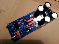
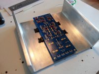
Finally, after having read the full thread, I feel brave enough to share a picture of my yet unfinished DCB1. I am still lacking some essential parts and due to holiday economics and home refurbishing it will remain unfinished for quite a while.
The chassis/heatsink is an aluminum U-beam I got from work. I am tinkering with the idea of making a nice wood enclosure.
Finally, after having read the full thread, I feel brave enough to share a picture of my yet unfinished DCB1. I am still lacking some essential parts and due to holiday economics and home refurbishing it will remain unfinished for quite a while.
An externally hosted image should be here but it was not working when we last tested it.
An externally hosted image should be here but it was not working when we last tested it.
The chassis/heatsink is an aluminum U-beam I got from work. I am tinkering with the idea of making a nice wood enclosure.

Hi all,
I'm new to this thread and I'm looking forward to have my DCB1 ready. I have all the material I need and I'm in the process to build the shunt reg and buffer. I've tried to read as many pages of this thread as I could but I still have few questions, I hope you can redirect me to the right page.
1) the board and circuit I can see at the very beginning of the thread is still valid? any relevant change I lost in the next 500 pages?
2) I have 2 matched pairs of 2SK170 (the two pairs are pretty close), I guess I have to use the first matched pair as upper transistor and the second matched pair as lower transistor, so that the left and right channels of the buffer are balanced... right?
3) the rest of the 2SK170 I have (10 in total) are not matched, but looking at the BoM it seems that is not a requirement. How should I pick the remaining 6 guys out of my 10? any best practise?
Build the PSU first and check the smoothed voltages.
Power it via a Mains Bulb Tester until everything has been checked at every power ON.
Add on the shunt regulator and check the voltages at the 3 pins in the middle. If you solder copper hooks here you can attach probes that won't slip.
Then add on the Buffer and check voltages again. If you solder in SIL sockets for the two sets of 6pins, you can use this to measure your jFETs and find those that give the lowest output offset.
Select two that are very close Idss. Place the lower Idss in the CCS position and place the very slightly higher Idss in the Follower position.
This should give a very low -ve output offset. If your offset is +ve then you have swapped the jFETs. This could simply be a placing mistake or it could be a measurement error due to Tj varying as the measurements are in progress. The on board measurement rules. That determines whether you have a close pair.
I gave a Feucht link in an earlier post today. Read it.
Of the remaining 6 jFETs only two (one in the +ve and one in the -ve) need to be high gm, low Pinch off voltage types, i.e. 2sk170 or similar.
The others can be lower gm types like bf244 and many others. But check the pin out.
Power it via a Mains Bulb Tester until everything has been checked at every power ON.
Add on the shunt regulator and check the voltages at the 3 pins in the middle. If you solder copper hooks here you can attach probes that won't slip.
Then add on the Buffer and check voltages again. If you solder in SIL sockets for the two sets of 6pins, you can use this to measure your jFETs and find those that give the lowest output offset.
No, at least that is my opinion.2) I have 2 matched pairs of 2SK170 (the two pairs are pretty close), I guess I have to use the first matched pair as upper transistor and the second matched pair as lower transistor, so that the left and right channels of the buffer are balanced... right?
Select two that are very close Idss. Place the lower Idss in the CCS position and place the very slightly higher Idss in the Follower position.
This should give a very low -ve output offset. If your offset is +ve then you have swapped the jFETs. This could simply be a placing mistake or it could be a measurement error due to Tj varying as the measurements are in progress. The on board measurement rules. That determines whether you have a close pair.
I gave a Feucht link in an earlier post today. Read it.
Of the remaining 6 jFETs only two (one in the +ve and one in the -ve) need to be high gm, low Pinch off voltage types, i.e. 2sk170 or similar.
The others can be lower gm types like bf244 and many others. But check the pin out.
Last edited:
1) the board and circuit I can see at the very beginning of the thread is still valid? any relevant change I lost in the next 500 pages?
Valid
Thanks for your quick and clear answers.
I have another question for you regarding the cap that bypass the string of LEDs.
I made a mistake when I ordered the material and now I have 0.022uF film cap instead of 0.22uF. I see from BoM that I could also use 10-100uF electrolytic that I have. But the values between film and electrolytic are so different that I was asking myself the real purpose of this element.
Also I have some spare old film cap in the range 0.1-10uF, is it better to use two of those instead of electrolytics?
Its a voltage reference filter capacitor. That's its purpose. The electrolytic makes the better filter for noise spec of the regs due to high bulk capacitance. Reported as subjectively preferable also when some used the regs section for powering digital projects. Even the Soekris discrete ladder DAC lately. Such gear is pickier about 1/F (mainly subsonic) rail noise. It takes much capacitance to filter a low impedance string of LEDS well enough that low.
On the other hand, enough of those who have used it solely as a line buffer, where nothing else subtly noise sensitive is powered from the on-board regs, found the film cap option more natural, especially on female voices rendering. Those 0.22uF Wima MKP10s you often see in pictures where picked by a small team of listeners as preferable among several easy to get and logically priced MKP caps for instance. You can't hear any noise with either light or heavy filtering on DCB1 anyway. Its about SQ. To keep everybody happy, I specified both options in the layout right from the start. In other words, listen to your options in hand and pick your favorite in the concept of your own system. Whatever you will try, film or electrolytic, apply best quality parts you trust. Its a noticeable circuit position.
On the other hand, enough of those who have used it solely as a line buffer, where nothing else subtly noise sensitive is powered from the on-board regs, found the film cap option more natural, especially on female voices rendering. Those 0.22uF Wima MKP10s you often see in pictures where picked by a small team of listeners as preferable among several easy to get and logically priced MKP caps for instance. You can't hear any noise with either light or heavy filtering on DCB1 anyway. Its about SQ. To keep everybody happy, I specified both options in the layout right from the start. In other words, listen to your options in hand and pick your favorite in the concept of your own system. Whatever you will try, film or electrolytic, apply best quality parts you trust. Its a noticeable circuit position.
I'm considering to use LDR as volume control before the B1 buffer, in this case should I remove/change the first two resistors (220/220K) of the buffer? I'm asking just because I'd like to make it as easier as possible. My idea is to have the "audio stage" (LDR+B1+input selector) on one board and the PSU (including a 12V and 5V output) on another board.
- Home
- Source & Line
- Analog Line Level
- Salas hotrodded blue DCB1 build