Hello,
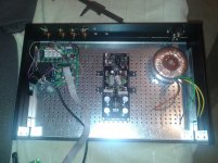
what do you think about using that metal chassis as heatsink for my hotrodded DCB1 ?
I'm thinking of using an aluminium metal plate to mount all 4 power transistors and everything to me mounted tight to the chassis.
Is a modushop case.
I plan to use 2.5R CCS resistors and 100VA transformer.
what do you think about using that metal chassis as heatsink for my hotrodded DCB1 ?
I'm thinking of using an aluminium metal plate to mount all 4 power transistors and everything to me mounted tight to the chassis.
Is a modushop case.
I plan to use 2.5R CCS resistors and 100VA transformer.
Attachments
Go ahead and try it, but only if you have a temperature probe to see how warm those IRF's get.
I have 2R, and it generates a lot of heat.
I use Aluminum angle, and heatsinks attached to that. It keeps heat evenly dissapated.
I suspect at 2.5R, you may get these too warm (65+)
I have 2R, and it generates a lot of heat.
I use Aluminum angle, and heatsinks attached to that. It keeps heat evenly dissapated.
I suspect at 2.5R, you may get these too warm (65+)
Go ahead and try it, but only if you have a temperature probe to see how warm those IRF's get.
I have 2R, and it generates a lot of heat.
I use Aluminum angle, and heatsinks attached to that. It keeps heat evenly dissapated.
I suspect at 2.5R, you may get these too warm (65+)
To damn hot
")
Leds not working
Hi friends,
I have just finished a hotrodded DCB1 kit from Tea-Bag and I have found a problem with the leds near 9240 Fet, they do not light at all.... The other ones are ok, the group of 3 and the other group of five leds light up correctly.
Any clue to start troubleshooting?
All the best,
Jorge
Hi friends,
I have just finished a hotrodded DCB1 kit from Tea-Bag and I have found a problem with the leds near 9240 Fet, they do not light at all.... The other ones are ok, the group of 3 and the other group of five leds light up correctly.
Any clue to start troubleshooting?
All the best,
Jorge
Leds not working
For being more clear, I am referring to the 5 leds group next to 9240 fet.
Thanks
Jorge
Hi friends,
I have just finished a hotrodded DCB1 kit from Tea-Bag and I have found a problem with the leds near 9240 Fet, they do not light at all.... The other ones are ok, the group of 3 and the other group of five leds light up correctly.
Any clue to start troubleshooting?
All the best,
Jorge
For being more clear, I am referring to the 5 leds group next to 9240 fet.
Thanks
Jorge
Leds not working
Ok. I will try it and report.
Thanks
It only takes one of them to be faulty or the wrong way round for all five not to light up. Try a battery and a series resistor across each LED in turn to see if they are all correct.
Ok. I will try it and report.
Thanks
Correct!!!
Hi,
I do not know how, but the four mosfets were stuffed wrongly. I was asleep I suppose... The 240 were in the 9240 place....I realized before firing up one of them swapped but no the other pair that were also misplaced.
Now al LEDs lit and I am obtaining 10.30 positive and 10.10 negative.
Thank you all, best regards,
Jorge
Make sure you have the 9240 and 240 in the right spots too...
Hi,
I do not know how, but the four mosfets were stuffed wrongly. I was asleep I suppose... The 240 were in the 9240 place....I realized before firing up one of them swapped but no the other pair that were also misplaced.
Now al LEDs lit and I am obtaining 10.30 positive and 10.10 negative.
Thank you all, best regards,
Jorge
Those are silicon pads, no mica needed.
and no thermal paste.
Thanks!
I just powered my DCB1. All LED's lit up as supposed. Voltages are +10.24V and -10.12V
De DC offset at the output measured 1.8 mV at the right output and 0.6mV at the left output.

The power MOSFETS stay nice and cool. I'm using 10R resistors. Maybe I will increase the current to 600mA.
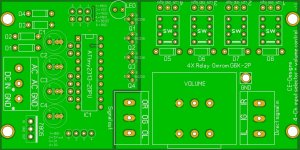
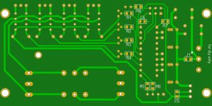
Yesterday I designed my own 4-ch input selection + volume control board. The PCB's are being manufactured this very moment. This will be used with the DCB1. It uses four G6K-2P small signal relays. The signals are being switched by using a ATtiny2313 with some BC338 transistors. A external 2-bit four position encoder connected to the ATtiny is used to select the desired input. It has a on-board 7812 based simplistic power supply that can be fed with both AC or DC current. The circuit that controls the relays is fully isolated from the audio signals and grounds. The potentiometer will be a blue 20K ALPS (no motor control). Hope I'll receive it soon. I will probably test the DBC1 first with just the pot in place
Attachments
Last edited:
I'm looking at building another Hotrod and have quite a stash of mid to high 10mA tightly grouped jfets, so was wondering if I could use these. I was looking at using them in the 4 matched group and the 6 unmatched. I know 7mah is preferred, i dont want to go out and by more unless I have to.
Thanks
Thanks
- Home
- Source & Line
- Analog Line Level
- Salas hotrodded blue DCB1 build