What would be the best option for the output coupling cap (need 6.8uF-10uF) from:
1.Obbligato Premium Gold ( I am afraid that they might not be a genuine caps from the China supplier on ebay)
2.Obbligato Premium Film Oil Caps, big cans with both leads on one side.
3.Obbligato Film
4.As Salas mentioned, collection of monstrous “250V PIO Capacitors K75-10” Russian capacitors to make necessary value bypassing with 0.1uF monstrous Russian Teflon “0.1uF 5% 600V teflon HI-END capacitors FT-3”
Also, 250V would be enough, no need to go to 600V if 250 available?
Would be a good option to use Obbligato Premium Film Oil (or Film or Gold) and bypass it with 0.1uF monstrous Russian Teflon “0.1uF 5% 600V teflon HI-END capacitors FT-3”?
According to Russian standard/marking style the 0.1uF 5% 600V teflon FT-3 as seen on the photo is 600VDC.
I can wholeheartedly confirm that K75-10 at 2.2 with 0.1 FT2 bypass sound more than terrific for my 220K amp.
However I cannot vouch for 7-10uF.. that s a huge value and I don t know how paralleling four or five of them could behave...Bypassing should also be at around 1/10th of the main cap so... ? I don t know if it s a very good idea... I won t be a cheap idea either...
Why do you need such a big cap anyway?
Maybe because he is feeding a pair of amplifiers each with a Zin of 20k.Why do you need such a big cap anyway?
6u8F & 10k would give an RC of 68ms and this would be below my acceptable lower limit for adequate bass reproduction.
My power amp's Zin is 25k, as Salas in the other tread recommended 6.8uF to 10uF cap value, and I woild agree that this is the right value to use.
Dimkasta, your 0.1uF bypass is FT3, not FT2, right?
I would use only single cap, no by passing, but my worry is that those big can Film Oil Caps have long foil lengt, resulting in large parasitic inductance acting as low pass filter.
This is why the bypass cap needs to be added in parallel.
My concern was in general to findout the best option between first thre Obligato caps.
I woudl appreciate for any ideas.
AndrewT, OK, inlight of this, still bypassing cap (Teflon for example) would be needed/suggested?
Which one of the"chemistry" would be best?
1.Obbligato Premium Gold
2.Obbligato Premium Film Oil Caps, big cans with both leads on one side.
3.Obbligato Film
4.Monstrous “250V PIO Capacitors K75-10” Russian capacitors
Which one of the"chemistry" would be best?
1.Obbligato Premium Gold
2.Obbligato Premium Film Oil Caps, big cans with both leads on one side.
3.Obbligato Film
4.Monstrous “250V PIO Capacitors K75-10” Russian capacitors
My bypass is FT3
That said and after more than a month with the russians I have to say that I am very very happy with them. However I can still perceive what the others were saying that the PIO brings the mids to the center of attention and do not go very very deep and very very high. Where they go however, they go with style and authority...
That is why I got the 0,47uF FT3 to try. But I guess I am lucky this way since my amp allows that low capacities with no significant penalty.
Google for "Orgy of capacitors" and you will find a very interesting thread that if I remember correctly also comments on Obbligatos bypassed with FT3 and Vcaps.
OK I have just replaced the K75-10/FT3 combo with a 0.47uF FT3.
I have not done any proper auditioning yet since it s late here in Greece, but from some low volume tests I can tell that the non broken in FT3s play at least as good as the broken in K75-10/FT3 combo, but I am pretty sure that FT3s already go higher and lower.
To be fair I have also replaced the output wiring with some nordost ribbon cabling, so part of the improvement could be due to that, but still...
I have received my boards from Tea-Bag and have started putting a DCB1 (BiB) together.
Just one simple question: Is a WIMA MKP4 1uF OK for suppressing the LED noise from the supply?
I see most people went for 0.22uF, but also see that I wide range of values is doable. I used the 1uF caps because I had some in my stock. Else I would have to add it to my current order that I am building up to Mouser. It's really painfull if you have to order $200 worth of stuff to get the $60 shipping free.
Would it hurt if I feed the circuit with a signal that has DC offset beyond 5 mV and place some coupling caps behind the DCB1? Or will it be better to get rid of any DC before the signal enters the DCB1?
I plan to use some power amps that make use of coupling caps and I do not like the idea of having multiple (unnecessary) coupling caps in the signal path.
I plan to use some power amps that make use of coupling caps and I do not like the idea of having multiple (unnecessary) coupling caps in the signal path.
I plan to use some power amps that make use of coupling caps and I do not like the idea of having multiple (unnecessary) coupling caps in the signal path.
One ac coupling in the chain should be enough.
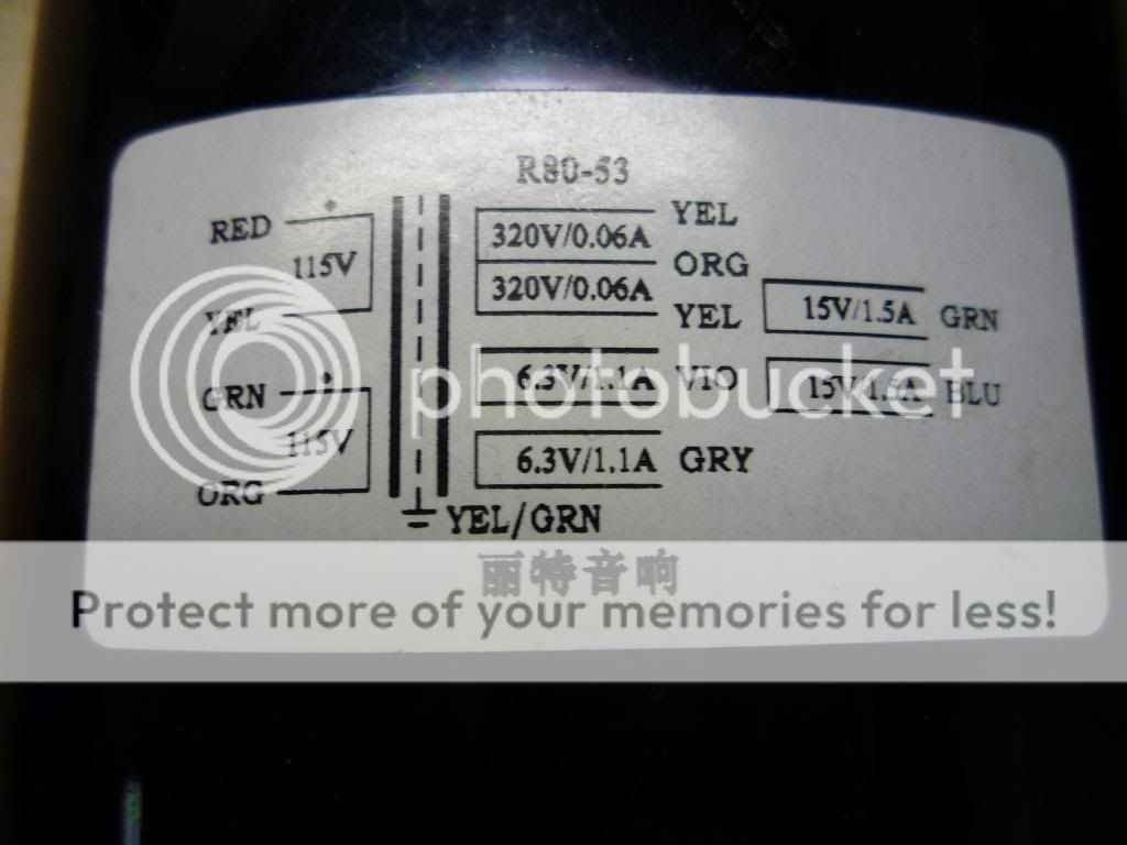
I got my RCore!
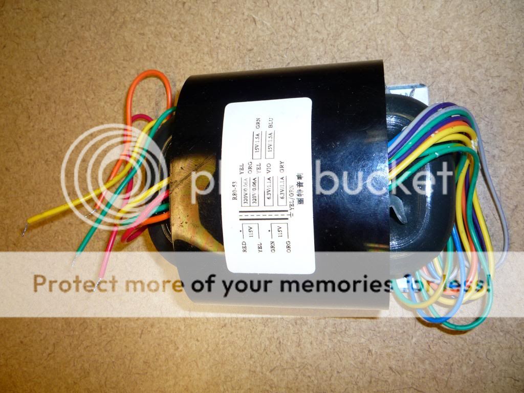
Questions on the hookup to 120 VAC
The wires to the fused IEC 120V. I have RED, YEL, GRN, ORG on the hookup side. What two do i wire to HOT(+) and what to Neut?
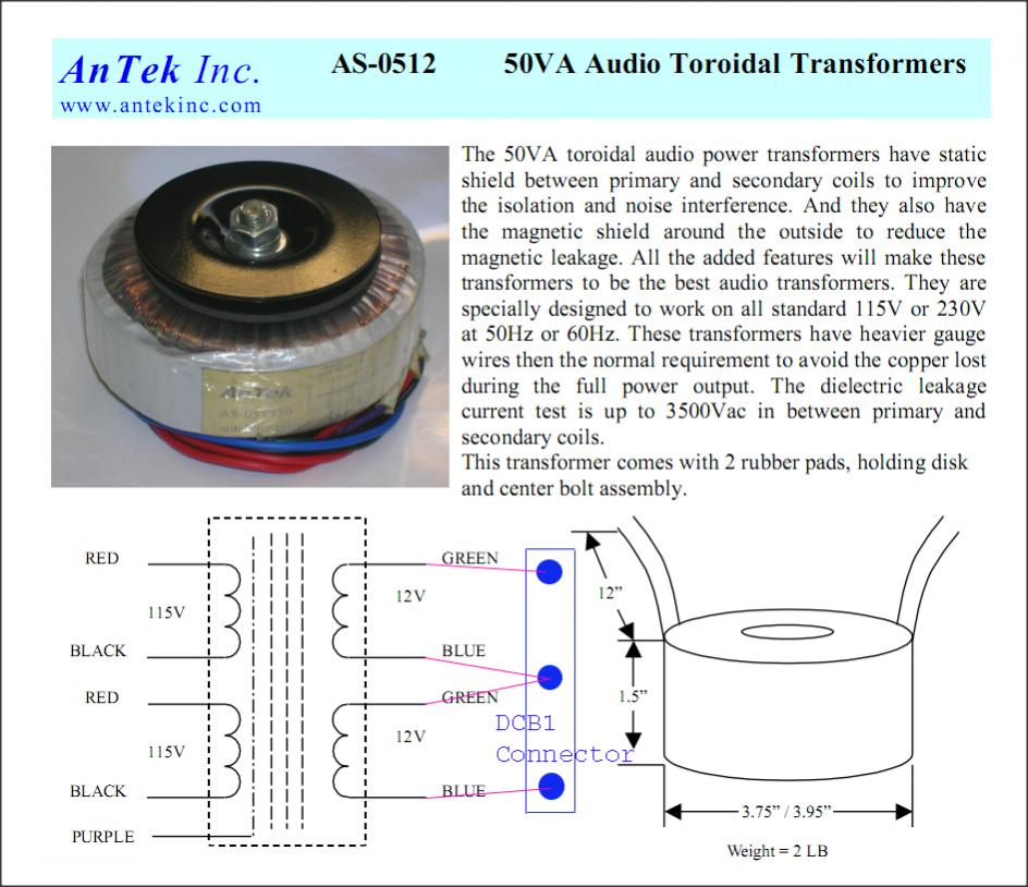
OUt the other side is the 15V to the DCB1. I have two BLU and two GRN wires on the RCORE output. Do I hook one GRN to the side O1 or O3, One BLU to the other side O1 or O3 and then a BLU and GRN to the center like this:
I then have 1 more YEL/GRN. Does this YEL/GRN run to the IEC Ground?
Thanks for the help!!! I got side tracked with some speaker project build and now I'm back to this!!!
Questions on the hookup to 120 VAC
The wires to the fused IEC 120V. I have RED, YEL, GRN, ORG on the hookup side. What two do i wire to HOT(+) and what to Neut?
OUt the other side is the 15V to the DCB1. I have two BLU and two GRN wires on the RCORE output. Do I hook one GRN to the side O1 or O3, One BLU to the other side O1 or O3 and then a BLU and GRN to the center like this:
I then have 1 more YEL/GRN. Does this YEL/GRN run to the IEC Ground?
Thanks for the help!!! I got side tracked with some speaker project build and now I'm back to this!!!
Red+green to live yellow+orange to neutral. Shield YEL/GRN goes to IEC ground. Output side has two blue and two green for 15+15V which is rather stupid because it does not help with identifying the middle wires as the windings go, so attach one green to one blue and make a middle point at random. If it buzzes at all combine another blue to another green. This Tx looks big and made for tube gear. Insulate the 320VAC HV outputs well and keep them properly tacked away. Use your DMM on AC to confirm that the 15-0-15VAC you created is there as expected on the wires to use before applying to DCB1.
I think I follow you. I have a DMM. So I think I can check a green and blue and if I see the 15VAC then I have one of the pairs... Then if I check the other pair of green and blue I should see the other 15VAC
If I have the wrong combo of green and blue I won't get the 15VAC on the DMM
sound right?
If I have the wrong combo of green and blue I won't get the 15VAC on the DMM
sound right?
First insulate the 320-0-320VAC triplet and keep away from those. Then apply the primaries to the wall power as discussed. Then confirm the 15VAC blue pair and the 15VAC green pair with DMM as individual 15VAC lines. Unplug from the wall. Combine one blue to one green 15VAC wire. Plug to the wall again. Confirm that you got 30VAC across the remaining free blue and green wires. Confirm half that voltage from each free blue and green end to common pair end. If any buzz emanates from the Tx change the wires that make up the common to another combo of green and blue.
- Home
- Source & Line
- Analog Line Level
- Salas hotrodded blue DCB1 build