Anyway, I'm a bit disappointed
It was not my meaning to crush your intentions. Here is a picture I found on Wikipedia showing the magnetic flux field around a toroidial transformer.

30 VA might work for a non hot rodded, depending on how the manufacturer counts on specs. (30 VA / (15+15)*1,4 is about 714 mA) As Salas says, dont give up, plug the current trafos in to your equipment and hold them in different ways to see if you can hear any EMI interference. It looks like on the pic that the trafos are mounted on some peice of metal. Maybe you can put that 90 degrees.
cheers!
I'll finish the project anyway, I was just a bit disappointed that it would take more time than I expected. Plus I assume that the chassis needs to be swapped to some decent one, not sure if I get any positive results with this one as there is no place even for a 50VA trafo that is usually 78+ mm.
Anyway, I'll make few more tests and report the results here on the following week.
thanks again!
Hi, if i build a DCB1 whats the chances of there being too much DC at the input, if i was using say a PC soundcard, a Tape Deck, or CD player ?
would putting one DC blocking cap on the input of each channel, defeat the purpose of having a DCB1 ?
I see a couple of DCB1's mentioned on Diyaudio, whats the main difference between them ?
Thanks
would putting one DC blocking cap on the input of each channel, defeat the purpose of having a DCB1 ?
I see a couple of DCB1's mentioned on Diyaudio, whats the main difference between them ?
Thanks
Well after "hotrodding" a bit and changing the 0.22 uf wimas for 0.33uf mundorf supreme silver in oil I did not notice any difference in sound.. Not better, not worse.
What is the rest of the system?
Hi, if i build a DCB1 whats the chances of there being too much DC at the input, if i was using say a PC soundcard, a Tape Deck, or CD player ?
would putting one DC blocking cap on the input of each channel, defeat the purpose of having a DCB1 ?
I see a couple of DCB1's mentioned on Diyaudio, whats the main difference between them ?
Thanks
Better put one cap on the output. You still got one coupling instead of two and shunt regulators. It partly defeats the purpose but not entirely in other words. If your amp has an input cap already you need no more. Chances with sources are they will not be usually having high DC offset but you should see that with your DMM in DC mode checking one by one their output.
") its all starting to make sense now !
its all starting to make sense now !Hi, diy almost all over the place.
Super tweaked Audio Note kit1 (double c cores etc) - well it is a bit retired now
Harrissons symef in my setup right now.
DCb1 and Super tweaked Audio Note linestage (double c core OPT's etc) - well trying a 12b4a circuit in it right now. Switching between these.
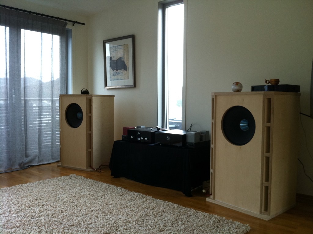
DIY "onken" Hemp Acoustics co15v speakers.. Some of the best I have ever heard and built.
DAC: Highly modified Audio Note..
An old picture.
Super tweaked Audio Note kit1 (double c cores etc) - well it is a bit retired now
Harrissons symef in my setup right now.
DCb1 and Super tweaked Audio Note linestage (double c core OPT's etc) - well trying a 12b4a circuit in it right now. Switching between these.
DIY "onken" Hemp Acoustics co15v speakers.. Some of the best I have ever heard and built.
DAC: Highly modified Audio Note..
An old picture.
What is the rest of the system?

I'm thinking about building in a boozehound phono preamp with a hotrodded DCB1. Any reason I can't tap into the shunt regulated power supply to power the phono? It's happy with anything between 12V and 24V DC so I think this would be ok. All I would have to do is add a switch for the line/phono RCA connectors.
It s also time for me to start testing output resistors, so Niko I need your help better optimizing their value.
If I remember correctly from one of your previous posts, you suggested feeding a wave into the buffer and checking for oscillations. If everything seems ok then try to lower the output resistor values (and output impedance) until oscillations appear, and then go a bit up until it's fixed.
Do you mind sharing a bit more about this testing rig? What should be attached to the output? Cable only? amp? dummy load equal to amp impedance? What should the test input wave be?
I have no generator, so I will have to use something like a plain wave generator either from my pc or my phone.
Also, could I use trimmers to find the lower value for the resistors?
Are these lower values dependent only on the input impedance of the amp, or by the interconnects as well?
Thanks again for your invaluable help
You need a clean square wave generator in the audio band at least with the fastest rise time you can have, the IC cables to be used, a dummy of the amp's input resistance and capacitance to terminate the IC cable. You need not see ringing on the edge of the square wave as you test lower output series resistor values.
I'm thinking about building in a boozehound phono preamp with a hotrodded DCB1. Any reason I can't tap into the shunt regulated power supply to power the phono? It's happy with anything between 12V and 24V DC so I think this would be ok. All I would have to do is add a switch for the line/phono RCA connectors.
The DCB1 is 10V out though.
In trouble with 2 hotrodded DCB1
Built 4 during last 3 months : two were perfect at first fire up and 2 others were not.
All semi conductors come same batch:BC550C,BC560C ,BC517G and ixys diodes from Digi-Key
Transformers 14-0-14 120va;and get 20.5VDC on can, resistors 10 ohm 5w , diodes from Ed.Lafontaine, IRFP240/9240 from an other DIY member etc. , 2sk 170 from Spencer
On one DCB1 the 5 diodes on 9240 side don't light on ; the other the 5 +3 diodes on same side (9240) don't light:
So at first ; what I am looking for ; what components I must suspect.
Where is DCB1 diagram on DIY
Thanks for your help.
Last edited:
- Home
- Source & Line
- Analog Line Level
- Salas hotrodded blue DCB1 build