I have been following the nCore thread for some time (a future project). The consensus is that the nCore SMPS is as good as a linear PS. Expensive, but it proves that a SMPS can be made well enough for audiophile applications.
For power amps surely. I haven't looked in to its specs like output impedance, its flatness, extension, rejection, and absolute noise so to know if it can be better than a Jung reg linear standard of performance for instance when looking for state of the art regs for low PSSR preamp circuits.
That ripple goes to 60mV peak to peak when it gives 1A. It receives linearly regulated DC input in the test, I don't know if it adds even more stuff if fed from just bridge and capacitor. Typical laptop bricks can be worse or bit better but that's the deal more or less. Silent SMPS are costly and sophisticated. Like those for Hypex Ncore amps.
Hi Salas,
Gee, I hadn't thought to look at that wave form,I bought some(10) of those from the manufacture S-ure for some audio use ,maybe some r's and caps would smoothe it out? or build some more Salas shunts and don't worry about that problem,lol

NS
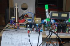
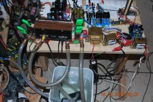
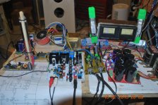
here's my setup with DCB1,It's on a board to help me get a cabinet layout Idea ,I am using 8 class A Fet amps.The cabinet will have 4 slide in/out draws ,with a 2 mono blocks per shelf ,with Power supplys outside of the box to help with the shielding and heat removel,I am real happy with the DCB1 works GREAT! The 2 amps in the pics are STD F5's that are water cooled as the rest will be also,They are running at 1.3 amp per fet and the water at the sinks are staying at 100 degrees ,I haven't added a radiator yet but will,I made the sinks from server copper heatsinks cut in half and covered with copper sheet and a outlet and inlet of .5" copper tube ,I'll need it with 2 f5's for tweeters,2 F5 turbo's for mids,2 F5 turbo's for Mid bass and 2 V3's for xoc1's subs, almost all is ready, soon they will all get to play together,LOL. The cabinet is being bent up this weekend,a little paint and some wiring ...........
Regards,
NS
Regards,
NS
Attachments
Hi Salas,
Gee, I hadn't thought to look at that wave form,I bought some(10) of those from the manufacture S-ure for some audio use ,maybe some r's and caps would smoothe it out? or build some more Salas shunts and don't worry about that problem,lol
NS
Surely smooth it out further and see results on the scope. There are circuits with low bandwidth and good PSRR that you may find them switchers enough for them. They are good for up to 10W power when the bottom is dissipating on a metal plate. Watch the temperature on the individual components on that tiny PCB though to know up to what amperage is good for the provided cooling. Tell tale borderline is when you can hear the 33uH SMD coil squealing loud enough.
here's my setup with DCB1,It's on a board to help me get a cabinet layout Idea ,I am using 8 class A Fet amps.The cabinet will have 4 slide in/out draws ,with a 2 mono blocks per shelf ,with Power supplys outside of the box to help with the shielding and heat removel,I am real happy with the DCB1 works GREAT! The 2 amps in the pics are STD F5's that are water cooled as the rest will be also,They are running at 1.3 amp per fet and the water at the sinks are staying at 100 degrees ,I haven't added a radiator yet but will,I made the sinks from server copper heatsinks cut in half and covered with copper sheet and a outlet and inlet of .5" copper tube ,I'll need it with 2 f5's for tweeters,2 F5 turbo's for mids,2 F5 turbo's for Mid bass and 2 V3's for xoc1's subs, almost all is ready, soon they will all get to play together,LOL. The cabinet is being bent up this weekend,a little paint and some wiring ...........
Regards,
NS
Steam punk feel diy stuff. Cool.
Steam punk feel diy stuff. Cool.
Indeed!
Hi, guys.
Nice looking work.
I have a quick question. I'm sure it's been addressed by now, just haven't had time to look through the entire thread.
It's this: Can the board be cut in two to separate the audio circuit from the power supply circuit? I'm almost sure this has been asked and answered at some point.
I have the black circuit board from the red, black, and white kit. I'm really interested in using the DCB1 to buffer the output of an optical volume control. Obviously, it is of great benefit to keep the hot power supply away from the LDRs, as they really drift with temperature.
My desire is to house the power supply in an outboard box and connect it to the optical control/buffer via an umbilical cord.
Can it be done?
Thanks!
I chopped up a mesmerize board with a chopsaw, and used just the channel switcher part and then with another chop, isolated just the positive rail to power the leds in my optical resistor volume control. The negative channel went in the bin in this case.
(I added a full DCB1 hot-rod and a remote control volume pot for the opticoupler, and that is my current pre-amp.)
(I added a full DCB1 hot-rod and a remote control volume pot for the opticoupler, and that is my current pre-amp.)
Yes.
Awesome! Thanks.
I will look at the board closer when I have it in front of me. Can it be done with one straight cut across the board, or are there components that need to be cut around?
This is good new for keeping those LDRs cool while reaping the benefits of the hotrodded power supply.
Great!
Awesome! Thanks.
I will look at the board closer when I have it in front of me. Can it be done with one straight cut across the board, or are there components that need to be cut around?
This is good new for keeping those LDRs cool while reaping the benefits of the hotrodded power supply.
Great!
Like in the attachment. Feed 15V DC at the 100nF cap's pins under its pads for the output relay to work. Even raw DC will do. Watch the polarities by following the whole board as depicted. Feed +10-0-10VDC regulated under nearest pads that used to continue from the "Vout" auxiliary feed out taps connector. Cut carefully, use a vise, don't listen to any Cat Stevens while cutting. Its a relatively thick good quality FR4 board.
Attachments
I got my PCB1 from Teabag and I'm waiting on the kits so I can buy a kit from teabag.
Question - Advised to use a 10K Attenuator. Are you to run the Input RCA to the 10K Attenuator and then the Attenuator to the PCB1 OR are you to run the Input RCA to the PCB1 and then the PCB1 to the Attenuator?
I think the Attenuator run to the PCB1 and the PCB1 out. The thing I'm confused about... I would think you'd want a high 100K Attenuator in front of the PCB1 and if the attenuator was after the PCB1 then the 10K makes sense...
you want high input impedance so the buffer is easy to drive (so a 100K attenuator makes sense). You want low output impedance so the buffer can drive hard (so a 10K attenuator makes sense after the PCB1)
I hope I don't upset anyone saying this... Not trying to offend. I am coming from running tubes. I was thinking a plus of a buffer was a higher input impedance...
I have a source that has an ouput impedance higher than the 10-20K... Perhaps this isn't a good fit? A buffer with this low of an input impedance seems odd.
input Impedance: 200K Ω / output impedance: +/-180 Ω is something ballpark that seems better for a buffer... Say you have a source with a 10K output impedance... with the 10 to 1 rule you'd want the input impedance at 100 K I thought.
I am learning more about impedance... I'm pretty new. Not trying to offend here.
Thanks for the time Salas and all
More on my question in regards to the 10 to 20K input impedance possibly being low...
A BURSON buffer has Input impedance: 500 KOhms with Output impedance: line out 15 Ohms @ line level. This input impedance makes more sense to me... Not trying to sell or say the Burson is superior... Just noting the input impedance difference.
I like what the PCB1 has on the output impedance.. Just wonding if I have any way to get the input impedance up or if I'm worried about something that I should not worry about.
It has 220K input impedance as a buffer stage. When using a pot that puts series impedance in the equation, then it has an optimum range. In that case when needing attenuation also, its best to feed the high impedance source directly to DCB1 and use a 5K pot on its output. DCB1 can have 1 MegOhm even if the 220K input to ground resistors are changed to 1M. Any buffer won't have more input impedance than the pot if used before it. Here its the high capacitance JFETs used that pose a best bandwidth pot value limit VS BJT input buffers.
Ah, ok
220K input impedance sounds excellent! I'm kind of new to this as you probably can tell by now. Thanks again for the help Salas.
Just so I don't screw something up like I'm known to do
To get the 220K:
1 - RCA inputs wire to DCB1 Input
2 - DCB1 ouput wire to 5K pot/attenuator and pot/attenuator wire to RCA outputs
I do this and won't get the audible degradation you explained above?
Thanks again. You are quick!
One more question... I'm using this as a pure buffer... So I actually don't really want the attenuator at all.. Just a high input impedance like the 220K and then the output as low as possible.. I plan to build this with two pairs of RCA outs to drive two amps.
skip the pot entirely? tweeks to the PCB parts?
skip the pot entirely? tweeks to the PCB parts?
- Home
- Source & Line
- Analog Line Level
- Salas hotrodded blue DCB1 build