Thanks for adding up the numbers, Andrew.
Yes, I agree the heat must be managed. In all of my previous Tupperware projects, I have housed the transformer in a separate enclosure. Or used an outboard battery supply or off-the-shelf regulated supply. So the heat from the transformer was not an issue inside the plastic box. I expect that I'll try the same with the DCB1 and outboard the tranny.
Of course, I'm pretty much a rank novice at figuring out dissipation. With the tranny outboard, would a generously sized grid of small, closely spaced venting holes drilled into the lid and through the floor of the food container provide enough venting for the 2.6w from the stock DCB1 and regulator?
I must say, I am very excited about this project.
Last edited:
KT,
Been hangin' out at AudioKarma?
LOL
Ron
LOL,
Wow, I've been so busy the last few years that I dropped out of DIY. I'm just getting back in. Frankly, for the last several years, I forgot that AudioKarma even existed until you just mentioned it just now.
Is there something there I should see?
Last edited:
Why have we got an IC in a Salas topic Thread?A little off topic, but it concerns a question asked.
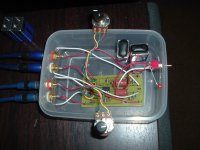
TupperWare!!!...........
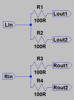
A parallel output with 100 Ohm buffer resistors in line.
I have double outputs to the amp and a self powered subwoofer, didn't use the 100R resistors. Seems to sound ok so far, have had no issues with it. Should I put the 100R resistors in anyaway?
I have had my 100R in for years, no gain problems. And not just in this project. I imagine it will tweak impendence a bit. I've had some very large resistors in line 10k on input before - you can calculate the voltage drop and gain with a t-network. Do not know the formula off the top of my head.
you can always do without, unless you run into some issues- then put them in.
you can always do without, unless you run into some issues- then put them in.
I was wondering the same thing. Wouldn't the 100R just act like an attenuator?
the reason TB has not notice any gain issue, or more correctly lack of gain is due to attenuation =I have had my 100R in for years, no gain problems. And not just in this project. I imagine it will tweak impendence a bit. I've had some very large resistors in line 10k on input before - you can calculate the voltage drop and gain with a t-network. Do not know the formula off the top of my head.
20*[log 10k/{10k+100}] = 20*log0.99009 = 20*(-0.004321) = -0.086dB
The attenuation created by the 10k input impedance is less than 0.1dB.
If there was a 100k stage to be fed by the DCB1, then the attenuation <0.01dB, (actually -0.00868dB).
Stop worrying about next to nothing.
Last edited:
Hi all.. Thanks for this great thread.
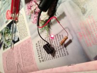
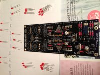
I received Tea Bags package some time before christmas and started soldering yesterday..
Some pics attached.
I have a couple of building questions:
As some people has mentioned before. The direction of the led's. I got a bit confused and have not soldered them yet. But they have been matched..
Is this correct?
Where 5 are gathered together. the square solder marks connects to the Cathode?
Where 3 are gathered together. the square solder marks connects to the Anode?
I have (on hand) 2 pcs identical 2*12v secondaries 15va toriods. Is this enough for testing purposes? I could maybe parallell them so I get 30va?
What is recommended V and va value on transformer for dcb1?
That is enough for now..
Attachments
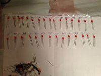
Is this correct?
Where 5 are gathered together. the square solder marks connects to the Cathode?
Where 3 are gathered together. the square solder marks connects to the Anode?
Vice versa.
I have (on hand) 2 pcs identical 2*12v secondaries 15va toriods. Is this enough for testing purposes? I could maybe parallell them so I get 30va?
What is recommended V and va value on transformer for dcb1?
For testing purposes and your 10 Ohm setting resistors, one Tx will be enough. To parallel successfully they should be well matched. A 50VA 15+15V Tx is good in general up to medium hot rod.
Vice versa.
Hehe - sorry of course
 - At work now and my mind is elsewhere...
Square hole is Led's anode in this pcb as crt designated that half circle symbol over the 5 Led groups, when its the cathode in the 3 Led groups. If you put just one in reverse they will not shine, but no reason to blow a reservoir cap. In fact its the first time I hear someone blows a reservoir cap. Could it be it was reversed for polarity by accidental insertion or just very unlucky to chance on a dodgy one?
Yes it was this post I was thinking of..
Sincerely
- Home
- Source & Line
- Analog Line Level
- Salas hotrodded blue DCB1 build