What part number of relay is that? Have you got a jumper where the PCB has "note" since you said its a 12V type? Have you installed the diode under the relay in the right way? BC517 and the proper relays by Omron, Nais TQ series, or NEC had 100% score of working together in the multitude of builds referred here at least. They normally take a couple of seconds to click.
Omron G6H-2 12V.
Sure I have a jumper and a diode in the right direction (it's actually some ultra fast 1A 40v Schottky, but there is no difference here I guess). I get exactly 12vdc after the reg, so should be something in BCs/ relay area. Will take a look again this evening for possible mistakes been made.
a darlington bc517 is not the correct way to switch a relay.
Use two separate transistors. A driver to tell the switcher to activate the relay coil.
Set the switcher to ~hFE=10 for lowest Vsat (10mV to 100mV) while ON.
The lowest Vsat for darlington is ~700mV and that is a big proportion of a 5V supply feeding a 5V relay coil.
Andrew, I like you replies very much! it's plenty of new terms & things for me to clarify every time!

So just to recapitulate, as a workaround could I substitute BC517 with two spare sk170bl (2nd with idss>10 as a switcher?!) or I didn't get the point regarding switcher's current gain ratio (hFE).
P.S. Change that BC550 to any pin compatible NPN or just another 550 sample, and verify the resistor values in the relay circuit too, if all else is not suspicious.
thanks! will do that!
Last edited:
Why have you got four heatsinks? Two should easilly suffice.
Also I hope you aim to mount the sinks so that the fins are vertical and have a free air flow through the fins.
Well I have done some testing and the present heatsink layout is adequate with hopefully enough headroom to compensate for enclosing everything in box.
I know vertical fins are better, but it will significantly reduce the contact surface with the bottom plate (to which the fets are attached).
There are also 2 heatsinks attached at the bottom of the plate, and the plate/side walls are elevated 3cms to allow it to breath from the sides
About air circulation, I intent to open some slots on the side walls to allow air flow in. And the top will be open in the middle, forcing the air move from the bottom sides to the top center.
hFE refers to a normal BJT, not a jFET.
Use a bc546, 547, 548, 549, 560 etc. Any BJT with IC>=100mA and Ib>=10mA and Vce0>=30V . You can re-arrange the legs of BJTs that have a different pin out.
Ensure for a 5V relay, which has ~40mA of current demand, that the base of the BJT gets ~4mA for that hFE of ~10 for low Vsat.
Stick in a second BC to tell the switcher to turn on. This bjt can operate with an hFE >100 and since it's output (IC=IE=4mA) is 4mA, only 40uA, or much less if you use hFE~400 (the c suffix).
Another unhelpful post.
Last edited:

Change the diode to a normal one pls.
no
seriously I've swapped it to IN4002 and as there was no difference, so I put my ulta hi-end Schottky IN5819 back
Anyway, the problem has been solved by replacing BC550 with BC639, works flawlessly now! BC550 was kindly asked to leave the pcb and find some more cosy place in the rubbish bin...mkt cap also has been removed.
thanks again for the help, Salas
I've matched the leds (used sockets) so it's 10.89VDC on both rails now that makes me feel very happy! Next step - jfets.
CSS resistors shows 2.03vdc on positive and 2.18vdc on negative rail, is it fine? Does the difference exist due to the relay circuit?
Another unhelpful post.
I would say - another useful post. But I need some time to comprehend it
thanks Andrew!
yes, BC550C!
last few things (I hope so) to clarify, do I need thermal paste if I use Kapton?
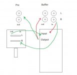
I'm going to add step attenuator that should be placed before the buffer as it was mentioned several hundred pages ago here However if I want to separate buffer from preamp (attenuator & buffer) is the wiring below correct in case that there always be only one source connected?
last few things (I hope so) to clarify, do I need thermal paste if I use Kapton?
I'm going to add step attenuator that should be placed before the buffer as it was mentioned several hundred pages ago here
However if I want to separate buffer from preamp (attenuator & buffer) is the wiring below correct in case that there always be only one source connected?Attachments
Don't know the thermal resistance of Kapton high temp tape. If its more than 1C/W that a common Silpad achieves, better avoid. Paste for Mica like films, yes. For Silpads, no.
I don't follow the above sketch easily, but in words, you should tap off from DCB1 (in) after the pot to a couple of extra outputs when needing non buffered attenuated outputs beyond the buffered attenuated normal ones you get from DCB1 (out).
I don't follow the above sketch easily, but in words, you should tap off from DCB1 (in) after the pot to a couple of extra outputs when needing non buffered attenuated outputs beyond the buffered attenuated normal ones you get from DCB1 (out).
Don't know the thermal resistance of Kapton high temp tape. If its more than 1C/W that a common Silpad achieves, better avoid. Paste for Mica like films, yes. For Silpads, no.
I don't follow the above sketch easily, but in words, you should tap off from DCB1 (in) after the pot to a couple of extra outputs when needing non buffered attenuated outputs beyond the buffered attenuated normal ones you get from DCB1 (out).
Hi Salas,
Do I need to apply any thermal paste like those we use on CPU heatsink for Silpad?
If its a hot rod and you use Mica, those for CPU are best, but see they are non conductive.
For Silpad NO. Makes it worse.
Then what should we use for white Silpad ?
Thanks
- Home
- Source & Line
- Analog Line Level
- Salas hotrodded blue DCB1 build