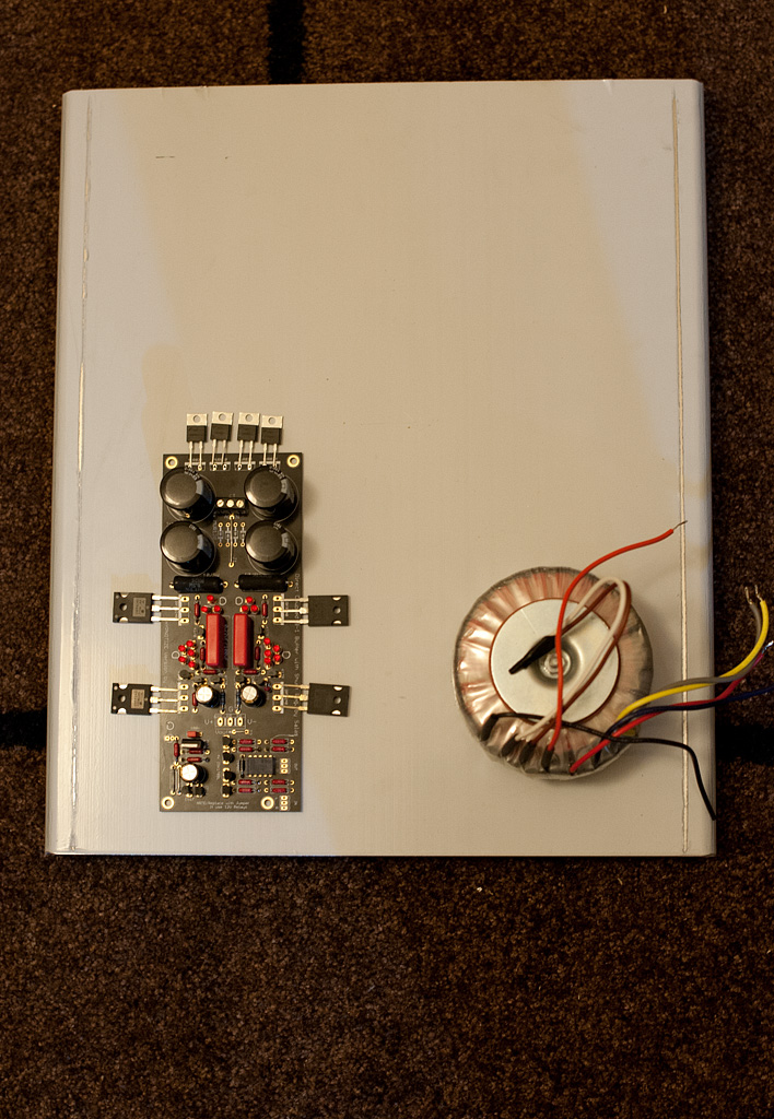
It' s a 40cm x 40cm aluminum plate 5mm thick and with around 3cms bent on the two sides to allow for easier mounting of side walls. It is very nice quality. Heavy and shinny. It even came with a sticky protective sheet on one side to prevent it from getting scratched.
I was planning to use them on my F5 monoblocks, but I always get some surplus")
I was planning to use them on my F5 monoblocks, but I always get some surplus
OK as promised here are some more photos from the current status
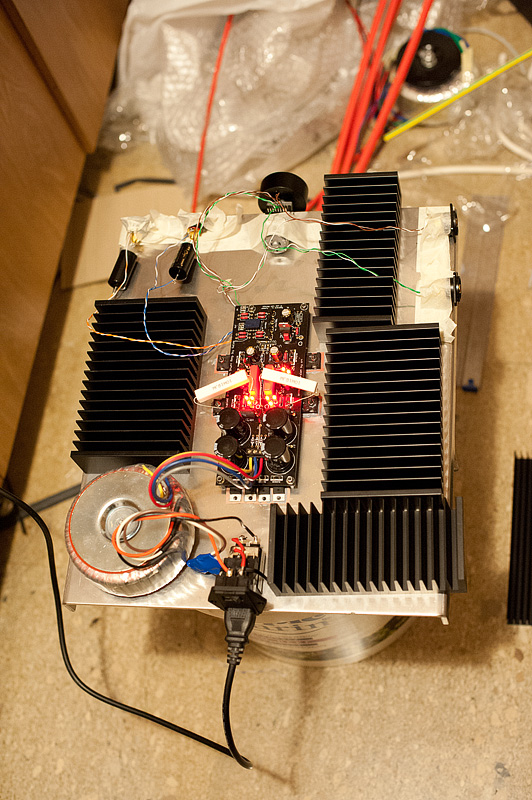
Here is the board with the 5x5R @5W resistors attached in parallel to the 10R Mills.

You can also see the additional heatsinks just thrown in there not firmly attached. The two bigger ones will go to left and right, and the two smaller ones will go top and bottom.
I also got two additional ones (you can see part of them on the right on the floor) that will go to the bottom of the plate and be attached using the same screws with the fets.
And here is another one with the lights on as it is now. Replaced the resistors with 1R @10W. Those still get pretty hot though....
Current measurements are
CCS resistance ~0R9
CCS current ~1,2A
With the single resistors and after hearing a song or two, I believe the thinness was fixed a bit. Still pretty early to make any serious comments with the freshly soldered parts. Anyway. just do not do any critical listening with chunks of cement resistors attached.
Here is the board with the 5x5R @5W resistors attached in parallel to the 10R Mills.
You can also see the additional heatsinks just thrown in there not firmly attached. The two bigger ones will go to left and right, and the two smaller ones will go top and bottom.
I also got two additional ones (you can see part of them on the right on the floor) that will go to the bottom of the plate and be attached using the same screws with the fets.
And here is another one with the lights on as it is now. Replaced the resistors with 1R @10W. Those still get pretty hot though....
Current measurements are
CCS resistance ~0R9
CCS current ~1,2A
With the single resistors and after hearing a song or two, I believe the thinness was fixed a bit. Still pretty early to make any serious comments with the freshly soldered parts. Anyway. just do not do any critical listening with chunks of cement resistors attached.
Attachments

Quick question. How hot are the 1R resistors supposed to run? The 10W ones I have, got pretty hot quickly. An hour later they were at around 70C
In your situation, I would read the spec sheet for that resistor from that vendor.
70c for a power resistor is usually okay.
Its 12W actually when having 1.2A through and 10V across each. 70C on the internal silicone die is safe. That means 50C on their cases you stick the thermocouple at in your config. For capacitors you gain life time inversely proportional to the ambient they live in. Double their half rated lifetime for each 10C less than their temp rating and add it up.
Its 12W actually when having 1.2A through and 10V across each.
Isn't it 1,2V across them?
The 20W will be on each Mosfet not on each setting resistor. We should only note that different leds or Mosfet batches may ask for lower than 1 Ohm to reach 2A.
So what wattage resistors will be needed for 2As?
I am asking because if we need 12W for 1,2A (10V across), I would expect something around 20W for 2A
So what wattage resistors will be needed for 2As?
I am asking because if we need 12W for 1,2A (10V across), I would expect something around 20W for 2A
#2370 I already wrote that the resistor dissipation is just what voltage is on the actual resistor times the set current. Measure your set resistor pin to pin, what is it? 1.2-1.4V now that you are set at 1.2A?
I don't know what you are expecting at over 1 amp... You're risking big time malfunction and something bad to happen to your audio equipment... Can you really hear a difference over 600-800mA?
Have fun!
Do
He uses an output coupling capacitor.
#2370 I already wrote that the resistor dissipation is just what voltage is on the actual resistor times the set current. Measure your set resistor pin to pin, what is it? 1.2-1.4V now that you are set at 1.2A?
That s what I thought, but I got confused from #2368 to #2370 where I asked if it was the measured 1,2V and you told me no it was 10V and 12W.
Anyway
So it's currently 1,1V x 1,2A = 1,32W on the resistors.
My initial question was if that 1,32W is enough to make 10W resistors run so hot? 70C on the cement body?
@Pinnocchio
Yes there is a difference, but I think 1-1,2A will be my limit mostly for practical reasons like heatsinking limitations and as you say general reliability and safety.
- Home
- Source & Line
- Analog Line Level
- Salas hotrodded blue DCB1 build