I have changed to BC517/BC550 but i dont have good news. First time didn't worked even the voltage acress relay coil increased from 0.8v to 1.4v. I shorted the 2x600R position and the relay clicked and it clicks on and of as i'm powering or disconneting power of DCB1 but there is no delay. I have installed anyway a 10R resistor in position of 2x600R and i have 4.4V acress relay coil. This circuit is really strange for me.
The goos news is that i have 0.2V difference between the two rails and DC out is very low 0.01\0.025
The goos news is that i have 0.2V difference between the two rails and DC out is very low 0.01\0.025
Good news, now is working and the problem was the orientation of the transistors wich in the first page of this thread is in the oposite way.
Thank you very much Salas for your support.
In this last picture i see also the GND is connected to the relay wich was not in the other pictures seen on the thread.
Thank you very much Salas for your support.
In this last picture i see also the GND is connected to the relay wich was not in the other pictures seen on the thread.
HEAT!
Hi There,
I built one of the buffers into a really nice 10mm thick aluminum case, and after experimenting with the current regulating resistor, settled on 10ohms.
I leave my pre-amp on all the time and wondered about the heat dissipation, as the case seems to get hotter when I have no signal going through the B1. At very low volumes it is quite cool and it then seems to heat up again when I am playing decent volumes.
Obviously I cannot feel immediate temp changes and am making these observations after several hours in each volume/playback state.
does anyone have an explanation of this behavior? Is it a side effect of the current flow when idle, similar to class A?
Brad
Can you show a picture of the build? Idle PSU current is very high VS what the signal asks for, heat should be even enough after warm up and in box equilibrium. To make sure you should time it and note down readings from a thermocouple or IR gun on a specific spot. Also room temp should be comparable. Turn off power amp, give DCB1 an hour of full volume play from cool. Read temp on what is the hottest spot on its closed case. Turn off DCB1, let it reach room temp. Turn on without signal for an hour, keep power amp off, measure DCB1's case temp again. Note down room temp in audio rack's vicinity during those tests at start and end.
Change in mains voltage will make a big difference to dissipation.
Increase in mains voltage from UK's min of 226Vac to UK's max of 254Vac increases the dissipation by ~+26%.
The UK's supply should rarely and probably never arrive between 216Vac and 226Vac. That would indicate a fault, even though it is within specified tolerance.
Increase in mains voltage from UK's min of 226Vac to UK's max of 254Vac increases the dissipation by ~+26%.
The UK's supply should rarely and probably never arrive between 216Vac and 226Vac. That would indicate a fault, even though it is within specified tolerance.
Last edited:
cheers Andrew + Salas for the QUICK replies.
the buffer works really well, and my post was to get a bit of an insight into the temperature variations. It never gets scary hot!
It did seem strange that the case felt hotter 1st thing in the morning, even though no signal was being passed, but maybe your thoughts Andrew are right on the UK mains variations.
During the day when the ambient temps are generally higher, the case usually feels cooler to the touch, even though it is generally being used.
I will try out your suggestions Salas and report back.
Brad
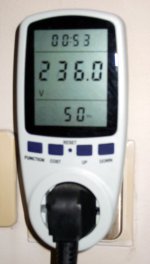
If there is big mains play indeed in his grid, what you say Andrew can give significant dissipation differences no doubt. He must use his DMM on his mains also then and keep notes. Which I don't generally recommend if with cheap non trusted for input protection DMM. I have this thingy on my a/v rig by the way. I see only about 1-2V differences in my mains over the week. Also shows Hz, power consumption, so I can see each item's Watt draw and all together, I can give it kWh price and it can tell me the rig's energy cost over a period etc. And its always 50Hz spot on, good for my ac TT motor.
Attachments
Salas, you must have a miracle worker controlling your mains electricity supply.
Worker must have gone to watch football, I saw +/-2.5VAC tolerance this weekend.
")
I am a total new comer to this. How do you match these pieces?
Just want to know I have 10 of them.
Thanks for your patience.
Recently discussed again there: http://www.diyaudio.com/forums/analogue-source/129126-simplistic-njfet-riaa-772.html#post3052749
- Home
- Source & Line
- Analog Line Level
- Salas hotrodded blue DCB1 build