Well, I wanted to be able to control each channel individually and all six channels as a group - though it is possible to control the output of each channel from my current DVD/SACD player. I have considered each pot as a receiver and a transmitter, but I know practically nothing about electronics design (it shows, I know) so I don't really know how to improve on the DACT layout. I'll keep the cables between short as possible, for one thing. Perhaps different values for the pots would work better? I'm under the impression that inputs should exhibit higher impedance than the outputs connected to them, so maybe I should use 10k then 20K? Salas cautioned against using more than 20K in series - is this 20K total (including the signal shunted to ground) or does only the resistance actually in the circuit at any one setting (disregarding resistance to ground)? Or maybe I should just can the individual channel controls and control them electronically from the DVD player? After all, once they're set they can be left alone.
I do want this to be well planned, but not being any kind of electrical engineer I appreciate help from all sources.
I do want this to be well planned, but not being any kind of electrical engineer I appreciate help from all sources.
Last edited:
I'm using the six analog outputs from my DVD player - two main (first DCB1 board), center, sub/LFE (second DCB1 board) and two surrounds (third board). The six individual pots are to adjust the relative levels of each channel for my room. My current A/V preamp does this automatically - that's nice but the overall sound quality, while quite good, could be better - that's why I'm thinking of this project.
Are the 6 individual pots for trimming the channel voltages to match sensitivities or similar?
Are your sources sending 6channel information?
Sorry to be so wordy - I meant to say "yes" and "yes".

then I suggest you use inverting opamps as your trimming adjustments. these can be set up for gain or attenuation. You can also easily restrict the total range of adjustment.
These "inverting buffers" present very low impedance to the inputs of the attenuators. This ensures that the 6gang attenuator attenuates equally on all 6 channels.
These "inverting buffers" present very low impedance to the inputs of the attenuators. This ensures that the 6gang attenuator attenuates equally on all 6 channels.
How about something like this (see attachment, figure A)? I assume that in order to make this adjustable one would put a trimpot where R2 is - or should I use a pot in place of R1 and R2? I suppose the total resistance should remain the same. So that would mean just associating the individual level pots with an opamp rather than sticking them in there by themselves - is that correct?
Attachments
then I suggest you use inverting opamps as your trimming adjustments. these can be set up for gain or attenuation. You can also easily restrict the total range of adjustment.
These "inverting buffers" present very low impedance to the inputs of the attenuators. This ensures that the 6gang attenuator attenuates equally on all 6 channels.
I alsways learn something from you Andrew!
post1847
The left most diagram, inverting, is the one you should use.
R1 & R2 set the gain or attenuation.
With both equal to 10k the amplification factor is 1 or +0dB.
You can alter the gain by simply increasing R2. 30k will give ~+10dB.
or
You can increase attenuation by reducing R2. 3k will give ~-10dB.
That range for a trimmer should be adequate for any sources you have or plan to buy in the future.
You can replace the resistors with a pot. The wiper goes to the -IN. But you must fit some protection in case the wiper goes momentarily open circuit.
You also need to add a fixed resistor before the pot at the input and a second fixed resistor after the pot on the leg going to the output feedback tapping. These resistors limit the range of adjustment.
You can choose any range of adjustment that suits your gear.
+0dB to -20dB or +12dB to -12dB or whatever.
You must use a unity gain stable opamp, or a unity gain stable discrete opamp.
I suggest you use a socket and a cheap & good {NE5534an+compensation}, to get you started. Later you can decide to go swapping or go discrete. Or 5532 for two channels and without added compensation.
How about something like this (see attachment, figure A)? I assume that in order to make this adjustable one would put a trimpot where R2 is - or should I use a pot in place of R1 and R2? I suppose the total resistance should remain the same. So that would mean just associating the individual level pots with an opamp rather than sticking them in there by themselves - is that correct?
It's normally consdiered bad practice to put a variable resistor (as opposed to a trim pot) in the feedback loop of an op-amp.
In the feedback position, this can result in quite noisy operation. (I'm talking about a volume type pot. that is constantly being adjusted.)
The normal practice is to attenuate at either the input or the output.
How about a sealed cermet trimpot? After all I'm most likely going to set these pots once and forget them.
post1847
The left most diagram, inverting, is the one you should use.
R1 & R2 set the gain or attenuation.
With both equal to 10k the amplification factor is 1 or +0dB.
You can alter the gain by simply increasing R2. 30k will give ~+10dB.
or
You can increase attenuation by reducing R2. 3k will give ~-10dB.
That range for a trimmer should be adequate for any sources you have or plan to buy in the future.
You can replace the resistors with a pot. The wiper goes to the -IN. But you must fit some protection in case the wiper goes momentarily open circuit.
You also need to add a fixed resistor before the pot at the input and a second fixed resistor after the pot on the leg going to the output feedback tapping. These resistors limit the range of adjustment.
You can choose any range of adjustment that suits your gear.
+0dB to -20dB or +12dB to -12dB or whatever.
You must use a unity gain stable opamp, or a unity gain stable discrete opamp.
I suggest you use a socket and a cheap & good {NE5534an+compensation}, to get you started. Later you can decide to go swapping or go discrete. Or 5532 for two channels and without added compensation.
OK great - thanks Andrew T - I think I have enough info to start trying things once I get the boards stuffed.
If you are going to set and forget then that is fine.
Just imagine an infinite gain amplifier (an ideal op-amp) with a dodgy connection (a variable resistor) in its feedback loop.
As you adjust the pot. the gain can vary from (say) 1 to (say) 1000000. The slightest crackle will be immediately amplified over 1 million times.
Personally I would use the pot to ascertain the fixed resistor that you need.
Last edited:
If you are going to set and forget then that is fine.
Just imagine an infinite gain amplifier (an ideal op-amp) with a dodgy connection (a variable resistor) in its feedback loop.
As you adjust the pot. the gain can vary from (say) 1 to (say) 1000000. The slightest crackle will be immediately amplified over 1 million times.
Personally I would use the pot to ascertain the fixed resistor that you need.
Ideally, yes - but I may have to use it in another room some day, in which case I'd have to reset it.
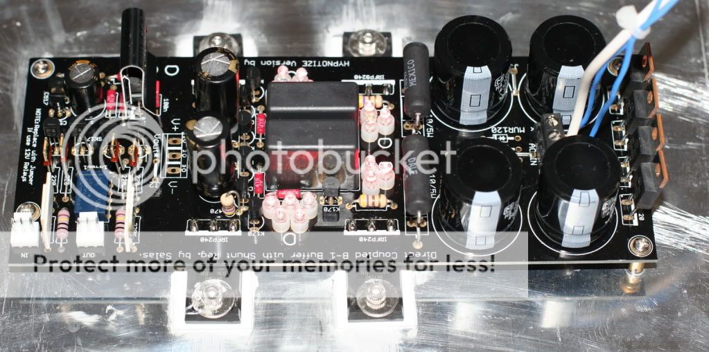
Just finish building the DCB1
Neg rail measure 10.06VDC
Voltage drop across the 10R is 1.909V
Pos rail measure 10.3 VDV
Voltage drop across the 10R is 2.028V
DC offset
Left 2.0mV
Right 1.6mV
AC input 16.52 and 16.54VAC
The relay kicks in 15 sec after power on. Next thing is to connect a 20k volume and start the listen test.
Neg rail measure 10.06VDC
Voltage drop across the 10R is 1.909V
Pos rail measure 10.3 VDV
Voltage drop across the 10R is 2.028V
DC offset
Left 2.0mV
Right 1.6mV
AC input 16.52 and 16.54VAC
The relay kicks in 15 sec after power on. Next thing is to connect a 20k volume and start the listen test.
Last edited:

If you are using 5V relays without current saver and a mesmerize then a sink may be necessary.
But a Hypnotize with a 12V relay should not require a sink on the regulator. If you add a current saver then both Hyp & Mes should not need a sink for 12V relays.
I have a Mes running day and night on 15+15Vac, with two 12V relays pulled in, a current saver active and the reg without sink, is running cooler than my finger, i.e. Tc<36°C
Last edited:
- Home
- Source & Line
- Analog Line Level
- Salas hotrodded blue DCB1 build