Thank you, Andrew!
I'm doing more testing with cheap speakers.
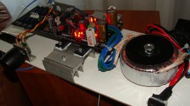
I realized the right channel of my DCB1 is dead. Not sure why. Both channels were working before, but after i unmounted the pcb from the chassis because i wanted to mount the mosfets to the bottom of the chassis, i connected everything back and voila, no sound on the right channel.
The offset on the right channel is suspiciously low (1 mv vs 3-4 mv on the left?), makes me wonder if it's even working. Voltage across both resistors are in range; voltage across the mains (?) is ~ +/- 9.50.
Not too sure what else to check. Possible that i fried the volume pot while dismantling everything? Is there any way to check? Pretty sure my solder joints are good.
Also, after mounting the mosfets to the bottom of the chassis, i realize the chassis doesn't seem to get that warm at all. I'm using the first level hot rod option. I used normal screws + nuts - is that not sufficient to maintain decent contact?
What parts should be changed to get offset as close to 0 as possible? Help is much appreciated!
I'm doing more testing with cheap speakers.
I realized the right channel of my DCB1 is dead. Not sure why. Both channels were working before, but after i unmounted the pcb from the chassis because i wanted to mount the mosfets to the bottom of the chassis, i connected everything back and voila, no sound on the right channel.
The offset on the right channel is suspiciously low (1 mv vs 3-4 mv on the left?), makes me wonder if it's even working. Voltage across both resistors are in range; voltage across the mains (?) is ~ +/- 9.50.
Not too sure what else to check. Possible that i fried the volume pot while dismantling everything? Is there any way to check? Pretty sure my solder joints are good.
Also, after mounting the mosfets to the bottom of the chassis, i realize the chassis doesn't seem to get that warm at all. I'm using the first level hot rod option. I used normal screws + nuts - is that not sufficient to maintain decent contact?
What parts should be changed to get offset as close to 0 as possible? Help is much appreciated!
Meaning to say the 2SK170s right? I took out the board, redid all the solder connections. Still the same result. But i realized if i turn up the volume loud enough, the 'silent' channel does have a *tiny* bit of sound. Really, really soft though, almost inaudible (hands can feel mild vibration of cabinet).
If it's the fet, it makes me wonder how they were spoilt in the first place.. since it was working fine before.. hmm. Could it be a potential relay problem? I'm not sure if i'm imagining things but the relay seems to take a longer time to click. Or is that related to a faulty fet, if any?
Since the voltage points measure properly, is it safe to say i didn't fry the mosfets and they're working fine? Or do i need to change them as well?
Will matching of the 2SK170s help with the offset? Since i'm going to change the FETs then i might as well shoot for as low offset as i possibly can...
Some discharge when you were handling the boards maybe, can't say. You need to feed signal and follow it, to see where it stops. If you don't have an oscope, DVM on ACV can detect. Feed 300Hz (test CD, or there are software generators free, google up) at about 1VRMS and see until where it makes it by probing the path, starting from input RCA, finishing at output RCA including interconnect cables. With DVM on Ohm you can check continuity, if relay engages, etc. 100% audio circuit jfet matching helps offset naturally.
"Each channel of the A 21 has a high-quality protection relay with gold-plated contacts for long-term reliability. These relays function to protect either the amplifier, the speakers, or both. When the A 21 is first powered on, these relays remain open for three seconds as the positive and negative power supplies stabilize and reach equilibrium ...
Specialized current-sensing transistors are connected to the output stages of the A 21 to constantly monitor the current flow through the output transistors. If the current drawn by this stage exceeds a predetermined safe level due to a load impedance below 1 ohm or a short circuit at the speaker terminals, the output relay will open immediately to prevent any of the output transistors or other parts from failing.
Each channel of the amplifier has a separate fuse for its positive and negative DC voltage rails. These fuses provide backup protection in case the over-current protection does not work in time, or if an internal part
fails. In the event of a part failure, these fuses halt operation to minimize damage to additional parts."
Not sure if it's only marketing fluff... with what the manual said, is it still advisable to use the DCB1 capless with the amp?
I can assume delayed output engagement to load and over-current sensing for automatic load disconnection, but DC output sensing I can't assume from that text. John Curl is posting in our forum all the time, maybe a PM or a post to him would clarify for sure.
Wow, thank you for all that detailed advice, Salas! Pardon me for being daft because i'm new to all this, but if a simple swapping of new parts will solve the problem.. i think i would prefer that, especially since the dcb1 was working fine before.. so i can't imagine something terribly went wrong? At least i hope nothing did, lol.Some discharge when you were handling the boards maybe, can't say. You need to feed signal and follow it, to see where it stops. If you don't have an oscope, DVM on ACV can detect. Feed 300Hz (test CD, or there are software generators free, google up) at about 1VRMS and see until where it makes it by probing the path, starting from input RCA, finishing at output RCA including interconnect cables. With DVM on Ohm you can check continuity, if relay engages, etc. 100% audio circuit jfet matching helps offset naturally.
So ... if i had to swap a part, it would be the 2sk170BLs? Are FETs very sensitive and easily damaged?
i will pm john to see what he says. Thank you once again!
The jFETs are not easily damaged.
I rarely use the heat shunt (sitting on the shelf) when soldering any semiconductors.
I handle all my FETs except opamps.
So far I cannot blame my bad handling/soldering methods for any failures.
Plenty of failures due to mis-connecting.
I think you have a broken connection somewhere.
If one or other of the jFETs had gone bad, then I don't think the output offset would be near zero.
So this time i tried taking out the male 3 pin molex at the output, to see if that was the problem because i was fiddling with the pins before and bent it quite a bit. Measured the right channel output directly at the pcb and the offset is ~ 0.. so the right channel is probably close to dead (since there is *very* slight sound) i guess? Possible relay problem? Looks like i'll have to do proper testing as Salas rightly advised!
 for now.I think i need bigger sinks
How hot do your heatsinks get?
Are the sinks large enough that the circuits & components survive for the two worst case faults?
Worst case for CCS mosFET is maximum mains voltage and shorted output.
Worst case for Shunt mosFET is open circuit output.
In both these fault situations the Amplifier is not working, so sound quality is not the issue. Survivability is the only issue.
Note, both these worst case situations cannot occur at the same time. With shorted output the sink only has to cool the CCS mosFET. The shunt mosFET is dissipating no power. You have a coupled sink. What is the dissipation of the normally operating stage. It has to dissipate and operate while the other half is in fault condition.
Last edited:
Thank you for your advice, Tea-Bag.I think the relay would cause a problem with both channels.
Measure agross the pins of 4 2SK's. D-S.
Is this the right way to test?
How to test FET’s-Jfet and Mosfet - Electronic Circuits and Diagram-Electronics Projects and Design
Am i supposed to test the 2sk while the dcb1 is on?
- Home
- Source & Line
- Analog Line Level
- Salas hotrodded blue DCB1 build