For 800mA of regulator output current, each diode passes the equivalent of ~810mArms of input current.
The datasheet shows the voltage drop for this current.
Multiply the current by the voltage drop to give the power dissipation (~560mW).
Check datasheet for Tc & Tj without a heatsink for this dissipation.
The datasheet shows the voltage drop for this current.
Multiply the current by the voltage drop to give the power dissipation (~560mW).
Check datasheet for Tc & Tj without a heatsink for this dissipation.
I bought a set of matched LEDs from Ed Lafontaine, and am wondering if there's any special way to arrange the LEDs? It comes in 2 sets. Do i have to arrange the red and yellow LEDs in a special way or it doesn't matter? Is the square shaped solder pad the cathode (-ve)?
http://imageshack.us/photo/my-images/15/img2759mk.jpg/
http://imageshack.us/photo/my-images/15/img2759mk.jpg/
An externally hosted image should be here but it was not working when we last tested it.
They can be arranged in any order. It is the cumulative Vdrop that matters. My use of yellow leds was to obtain matches closer to the target values than I would had I used all red. Some sets have green leds in them.
It looks like you received sets that I assembled from the marathon measuring session I did. ...not all sent out are that close... I have classified over 2000 leds up to this point. I've got another 900 when I need them.
It looks like you received sets that I assembled from the marathon measuring session I did. ...not all sent out are that close... I have classified over 2000 leds up to this point. I've got another 900 when I need them.
Thanks, Ed!
Does anyone have any transformer wiring tips? I'm not too sure how to wire it up properly. As per the BOM, i bought a 50va 2x15v toroidal. I'm on 230v, please ignore my country flag
http://docs-asia.electrocomponents.com/webdocs/0da0/0900766b80da0cc4.pdf
But for each secondary, there's only 2 wires with no center tap. Which way am i supposed to connect it?
ImageShack® - Online Photo and Video Hosting
ImageShack® - Online Photo and Video Hosting
Also, are there any other important things for me to take note of when wiring up the transformer and soldering to the iec/fuse? Any tips are really appreciated!
Last edited:
FIRST
Build a bulb tester.
Then insert all the transformer wires into separate receptacles of an insulated terminal strip. You will be working with 110/120Vac and a slip could kill you or your transformer.
Now wire up the transformer Primary fed via the bulb tester. All mains connections must be protected from touching.
Stand back and switch on mains power.
Switch off.
Tell us what the bulb showed.
Then we can talk you through the checking and measuring to ensure a safe wire up.
RE: LEDs on DCB1
Hi Ed,
You said,...
Ed (or Salas if he's reading)...
Is there an ideal voltage drop we are looking for, or are we just looking to match the drop of each channel?
Sorry for a dumb question, but late to the party and haven't got time to read the enormous number of pages here trying to find something relevent to my question! I am building the Hotrod version with the following mods:
Everything else is stock and I hope to run this thing as 'hot' (high current) as I can. Parts are still en route to me. I have some whopping heatsinks to waste on this thing, so heat dissipation shouldn't be an issue.
Hi Ed,
You said,...
It is the cumulative Vdrop that matters
Ed (or Salas if he's reading)...
Is there an ideal voltage drop we are looking for, or are we just looking to match the drop of each channel?
Sorry for a dumb question, but late to the party and haven't got time to read the enormous number of pages here trying to find something relevent to my question! I am building the Hotrod version with the following mods:
- Nichicon KG Super Through 4700Uf 50V caps
- Nichicon Fine Gold 100uF 63V
- 5W 10R resistors are Kiwame's
- BYC8-600 PSU rectifiers
Everything else is stock and I hope to run this thing as 'hot' (high current) as I can. Parts are still en route to me. I have some whopping heatsinks to waste on this thing, so heat dissipation shouldn't be an issue.
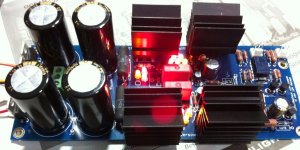
Finally wired up everything and took extra careful safety measures when hooking up the power. Seems to have powered up fine
Thank you, Salas and TeaBag for all the hard work you guys have put into the project! Not forgetting the thousands of DIYA members who contributed to this thread!
This is my first project so please forgive me for all my stupid questions.
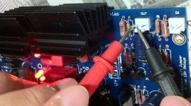
I tested the V+/V- and the values hover between +9.48 to +9.50 and -9.43 to -9.44. Are the values supposed to hover? I tested them after leaving it on for about 5 minutes. Did i do something wrong and is this perfectly normal?
I'm not sure how to test for dc offset. Is what i'm doing in the picture correct?
Thank you, Salas and TeaBag for all the hard work you guys have put into the project! Not forgetting the thousands of DIYA members who contributed to this thread!
This is my first project so please forgive me for all my stupid questions.
I tested the V+/V- and the values hover between +9.48 to +9.50 and -9.43 to -9.44. Are the values supposed to hover? I tested them after leaving it on for about 5 minutes. Did i do something wrong and is this perfectly normal?
I'm not sure how to test for dc offset. Is what i'm doing in the picture correct?
Attachments
Yes, normal voltages in my book. You might be able to get 10v or so with mixing around with LEDs, but the +/- difference is normal. Besides, you bought matched set from Ed, why bother.
-
DC offset meaurements look correct. output to ground voltage. Should be <10mv offset.
If it's way high, then don't hook it up to amp yet.
-
DC offset meaurements look correct. output to ground voltage. Should be <10mv offset.
If it's way high, then don't hook it up to amp yet.
Last edited:
I tested the V+/V- and the values hover between +9.48 to +9.50 and -9.43 to -9.44. Are the values supposed to hover? I tested them after leaving it on for about 5 minutes. Did i do something wrong and is this perfectly normal?
I'm not sure how to test for dc offset. Is what i'm doing in the picture correct?
Its looks like its the DVM's A/D converter to display translation not deciding the 3rd digit if the reading is somewhere in between. Not really a hover.
You put the probes OK for DC offset. How much?
I think you should ground the input (put the input at ground potential) to measure DC offset on the output. Please wait for some more expert comment.
There is no gain and a differential amp so it won't change much, but in general its correct to ground the input. Here we just do rough initial checks that the circuit isn't wrong though, and if there is some DC in a faulty case we better avoid since there is no capacitor. Not to stress a JFET.
I get 1.61v and 1.71v. While probing the leads of the resistors, my fingers slipped and some sparks flew. I should have been more careful, I think the resistor leads got burnt. Will it cause any problems?
I re-measured the V out and offset values and they seem fine, no change from before.
I re-measured the V out and offset values and they seem fine, no change from before.
Attachments

- Home
- Source & Line
- Analog Line Level
- Salas hotrodded blue DCB1 build