I have been running my B1 all week now and am very happy with the sound with 5w 10ohm wirewound hot-rod resistors.
I have just added a couple of spare 5w 10ohm resistors in parallel to the 10ohm ones already fitted and have been using the buffer for the last hour with no noticable increase in temperature. I may try some 1ohm wirewound resistors next.
Brad
I have just added a couple of spare 5w 10ohm resistors in parallel to the 10ohm ones already fitted and have been using the buffer for the last hour with no noticable increase in temperature. I may try some 1ohm wirewound resistors next.
Brad
Hi Salas,
only briefly, measured .1v which I thought must have been incorrect as I dont think that I got the DMM probes to connect properly and my DMM needs a new battery. I have now been running the B1 for a few housr and think that I can feel a slight increase in the temp on the outside of the case. Still sounds great as well.
will probably get 3.3ohm and 1 ohm wirewounds to try out at some point in the next few weeks and remove the boards from the case, so that I can fit the resistors properly.
Brad
yes.out of interest is there a situation where 5ohm resistors will produce a lower running current in the B1
when the Vdrop from DC supply to Vout drops below ~7V then the CCS becomes less and less capable of maintaining constant current.
The [/i]MINIMUM[/i] Vdrop in worst case conditions shoulde exceed 7V. That normally requires the operational Vdrop to be ~10V when mains voltage is "normal".
Hi,
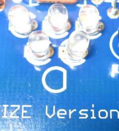
This thread is too long to search for, maybe someone ask before, sorry first, my question is about the led direction, I haven't receive the on going DCB1 pcb group buy just investigate the picture from website, I found the led symbol as attached pic on pcb but I never seen before, which side is the + and - , thanks.
This thread is too long to search for, maybe someone ask before, sorry first, my question is about the led direction, I haven't receive the on going DCB1 pcb group buy just investigate the picture from website, I found the led symbol as attached pic on pcb but I never seen before, which side is the + and - , thanks.
Last edited:
flat - cathode
round + anode
And to further clarify:
The anode (+) is the longer lead, with the rounded pictograph.
The cathode (-) is the shorter lead, with the flat back pictograph.
You should be able to verify this with a battery and a resistor (in series! to limit current) and be able to match the batches (either 3 or 5) of diodes for each half in voltage.
Anand.
just swapped out the current limiting resistors for 2.7 ohm wirewound ceramics. Measured 1.1v scross the negative side, which yields about 400ma. feeling the heat now. not sure if my dmm reading is really accurate as I need to change its battery - could be nearer to 600ma
for some reason I have lost the + side. the bank of 3 resistors is still lit but the bank of 5 are not lit. the relay still works. any ideas on what has blown?
its getting warmer here in the UK, so I want to see how far I can push the B1. the - side is not getting especially warm with the 2.7 ohm resistors. I have 1 ohm on standby once I sort out the + rail problem, still sounds good on 1/2 of its potential though.
Brad
Hi Salas,
all the LEDS are ok.
looks like either the MOSFET, of the 1st JFET. on the working side from the input end of the PCB I measure -21v,-9.5v and -24.5v the non working side gives 26.9, 26.9 and 21.6. the 1st SK170 reads -21.2, -21.2 and -0.7. the non working one gives 21.8, 0.7, and 0.7.
best Guess? I say JFET! what do you think?
Brad
- Home
- Source & Line
- Analog Line Level
- Salas hotrodded blue DCB1 build