IR a little better noise wise for sure. Normally lower Vf. Some red are good next, although there are some green or yellow that can be a bit better or worse, depends on make and batch. The yellow & green were usually more together for Vf but now there are some 1.8-1.9V red out there that seem to follow very well. Blue and ultra bright much more noise and high Vf. Between RGY classic leds no problem for this circuit. Its line level has unity gain and its CCS biased, has some rejection even. Its not about the bias LED in a head amp of a low MC phono to sweat much about. Just use the easier to get, near spec Vf, at least 20mA LEDS. I could normally use yellow as handier back when I developed and tuned the circuits.
Thanks Salas/Massimo - I think I'll just stick to my standard red LEDs then assuming they all measure correctly once I receive them. Failing that I've seen some yellows on Ebay that are 1.8 Vf at a good price - links below if it helps anyone:
50 LEDs- Ultra Bright Yellow 3mm LED 8000mcd Neon on eBay (end time 05-Jan-11 09:06:59 GMT)
Alternative: http://cgi.ebay.co.uk/50-WHITE-DIFF...ec_LightingLEDsStrobes_RL&hash=item2c58cc60d2
- John
50 LEDs- Ultra Bright Yellow 3mm LED 8000mcd Neon on eBay (end time 05-Jan-11 09:06:59 GMT)
Alternative: http://cgi.ebay.co.uk/50-WHITE-DIFF...ec_LightingLEDsStrobes_RL&hash=item2c58cc60d2
- John
Here is my source for 1.8v!!!!Thanks Salas/Massimo - I think I'll just stick to my standard red LEDs then assuming they all measure correctly once I receive them. Failing that I've seen some yellows on Ebay that are 1.8 Vf at a good price - links below if it helps anyone:
50 LEDs- Ultra Bright Yellow 3mm LED 8000mcd Neon on eBay (end time 05-Jan-11 09:06:59 GMT)
Alternative: 50 WHITE DIFFUSED YELLOW LEDs 250mcd 3mm led FRE RES on eBay (end time 14-Dec-10 13:08:48 GMT)
- John
100 Stk. LED 3mm rot (high efficiency red) on eBay (end time 02-Jan-11 21:21:04 GMT)
Thanks Salas 
I've only just finished Pass's original B1 so it'll be a couple months before I get to finish the DCB1 (finances & ill health - grrrrr!), but I'm looking forward to it from all the positive feedback I've read. And if I ever make it to Athens one day I'll have to get you a few drinks to say thank you
Cheers,
- John
Ahh I like your style, Sir! Haven't had Newcastle Brown Ale for a while... I wonder if they still have the indicator sticker gimmick on the side so you know you're drinking it at the preferred temperature? Then again in the weather we have here I think it's probably superfluous
As for myself I'll stick to Crabbies Alchoholic Ginger Beer - my current fav!
As for myself I'll stick to Crabbies Alchoholic Ginger Beer - my current fav!
Multiple buffers from one supply?
I'd like to build a DC buffer for a balanced system, ins and outs, so that's 8 channels. Would anyone who has built and tested this PCB know if I would need to build all of the power supplies, or could I run, say, all of the input buffers from one supply board and the same for the outputs? How detrimental would it be to run all of the buffers from one pair of supplies?
Many thanks,
BK
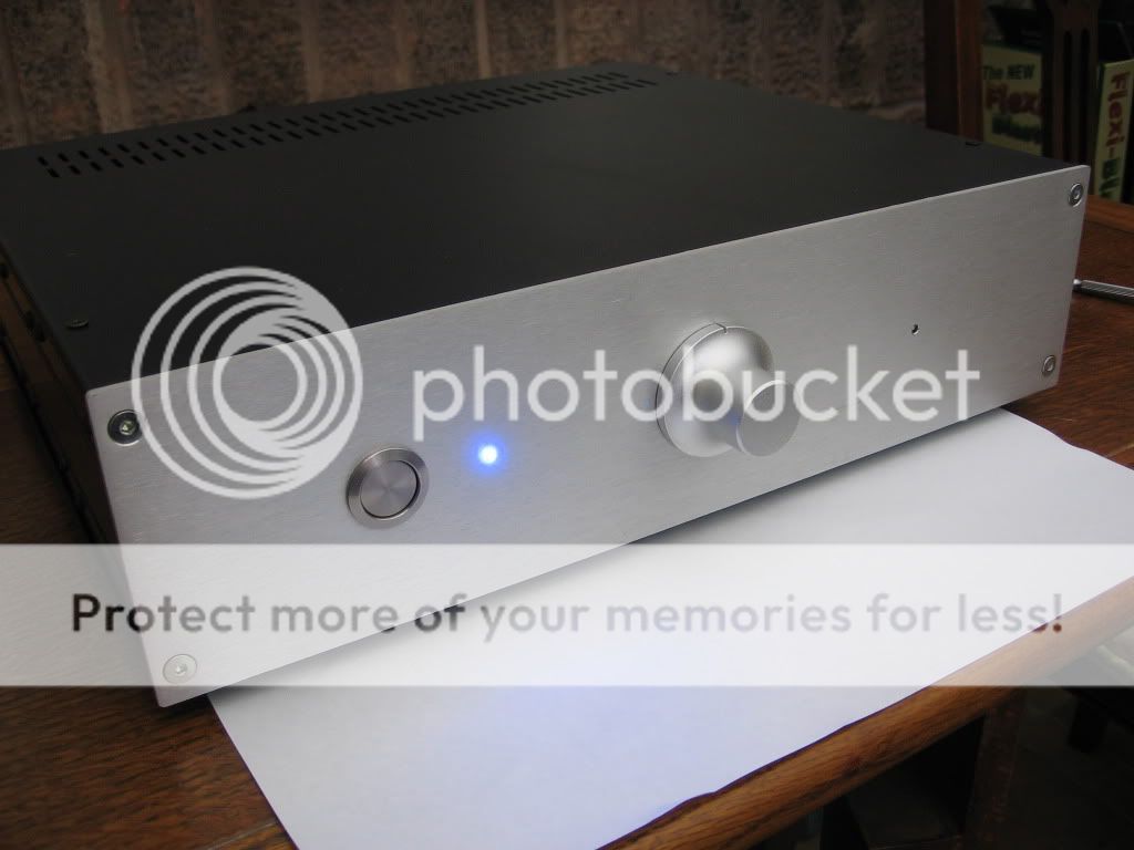
OK here it is at last, my all in one pre - DAC with Buffalo 24/Legato, DCB1 and Optical Volume control.
It works very well indeed, great sound. Please excuse the frightful wiring I fully intend to tidy it all up. This is just a lash up to see if all works.
It is interesting that comparison with and without the DCB1 is that the buffer pre adds substantial bass and somehow fills the sound out.
I have one slight problem, nothing major but it bugs me. The IRFP140 nearest the power supply runs a lot hotter than the other devices. It is within the 5 second touch test but the others are a lot cooler. What would this be? I guess i need to get a new batch and do a better selection of the LED's? The LED's selected were around the 1.63V mark tested using the diode test on my multimeter.
Voltage rails on the DCB1 are -9.14 / +9.15. Using 10R current setting resistors.
Is there an easy solution for the odd heat issue?
Anyway, I'm very happy and the whole thing is a great combination. Good work Salas!
Looks very nice, congratulations for your build. You mean one of the DCB1's 140 runs hotter or one in another supply? If it is a CCS 140, check the running current derived by the voltage on its setting resistor divided by the resistor's value. Not very big sinks and more enough mA due to maybe healthier leds, and/or weaker Vgs can combine.
P.S. If the above does not apply when you check, look also if the external filter board and wiring can be putting a CCS 140 into oscillation. Try a 0.1uF across V+ to GND where the wires land on the Blue if local steady state current does not explain the thermal difference.
P.S. If the above does not apply when you check, look also if the external filter board and wiring can be putting a CCS 140 into oscillation. Try a 0.1uF across V+ to GND where the wires land on the Blue if local steady state current does not explain the thermal difference.
Thanks Salas.
Yes I meant the DCB1 140 is hotter. I just checked and the Voltage across the 140 setting resistor is 2.014V (so around 200mA?) the other rail is 1.544V. So It looks like the positive rail (IRFP9140) is low?
I hadn't thought that the filter supply board may be causing the problem. I should possibly eliminate it by trying the recommended 4700uF caps on the blue pcb.
Should I get LED's with a forward voltage of 1.8V - 1.9V?
cheers
no, just change the resistor to bring the CCS current to match the other CCS.Voltage across the 140 setting resistor is 2.014V (so around 200mA?) the other rail is 1.544V..................
Should I get LED's with a forward voltage of 1.8V - 1.9V?
Thanks Salas.
Yes I meant the DCB1 140 is hotter. I just checked and the Voltage across the 140 setting resistor is 2.014V (so around 200mA?) the other rail is 1.544V. So It looks like the positive rail (IRFP9140) is low?
I hadn't thought that the filter supply board may be causing the problem. I should possibly eliminate it by trying the recommended 4700uF caps on the blue pcb.
Should I get LED's with a forward voltage of 1.8V - 1.9V?
cheers
Looks straight forward, its explainable by the current difference, not by oscillation. Do as Andrew said. Find balanced enough currents by trimming the setting resistors, and a comfortable to your sinks ballpark.
Nice one Andrew, should have thought of that. Obvious answer really! I'll probably have to wait until after the holidays to get some new resistors.
I shall bring the low current rail up to meet the other 200mA rail. Thanks guys, I now realise that the one I thought was too hot is fine, it's the other side that is too cool!
I'm a bit tired here and have a mental block - what value resistor should I aim for to balance the ccs?
Out of interest what would cause this imbalance?
Thanks again chaps
Different enough Vgs mainly and maybe happier leds contributing is the cause. Pretty natural, Mosfets vary for Vgs, you can easily hit upon a marked difference. I would target 180mA since with 200mA your sink gets a bit loaded. That would mean 2X22R 2W in parallel for the circa 2V side and 2X17R 2W in parallel for your 1.544V side.
- Home
- Source & Line
- Analog Line Level
- Salas hotrodded blue DCB1 build