Hi salas:
use +/- 20V DCin not too high voltage input?, because dcb1 just use +/- 10v DCin
mikeliu
Its better, although it will still regulate with lower difference.
Hi salas:
so we choose +/- 15V AC output trafo right?
Right.
Hi salas:
so we choose +/- 15V AC output trafo right?
Yes, use a 15-0-15 transformer if possible for 10V DC
1st power up
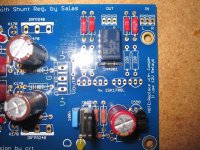
I am still waiting to the Texas Components TX2575 resistors, but the rest is ready to show ")
The other resistors are PRP9372 and the four 470R at the gates are Takman REX carbon film.
Because i´m also waiting to a special made shielded transformer, i use one of my 12V secondaries from my DAC project transformer for the 1st power up.
Everything works perfect!
An externally hosted image should be here but it was not working when we last tested it.
The other resistors are PRP9372 and the four 470R at the gates are Takman REX carbon film.
An externally hosted image should be here but it was not working when we last tested it.
An externally hosted image should be here but it was not working when we last tested it.
Because i´m also waiting to a special made shielded transformer, i use one of my 12V secondaries from my DAC project transformer for the 1st power up.
An externally hosted image should be here but it was not working when we last tested it.
Everything works perfect!
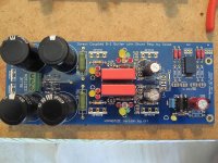
Nice big informative pictures. Is the heat on the small sinks comfortable with 22R CCS setting resistors? V+/V- OUT you hit close together?
The heatsinks are perfect. With only one 12VAC input i have +10,09 VDC and a -10,16 VDC at the outputs.
Thank you both and crt for this project!
Beautiful work!
Are your 220K resistors also TX2575's? Do they make single 220K resistors or are they a series daisy chain of several resistors?
See here to understand what I mean.
Anand.
That's some extremely extravagant components you're using there.
Is there a real advantage to using "audio signal path grade" resistors such as the PRPs for the shunt reg and delay? I have used bog-standard .6W metal film Vishay Sfernice for mine and Tea-Bag's supplied PRPs in the audio path. I will post pictures when I've finished the delay.
Also, what milli-ampage are you pulling with those Mills 22Rs? Was there a particular reason you chose not to stick with the 10R Dales?
Great pictures. Many thanks for that!
That's some extremely extravagant components you're using there.
Is there a real advantage to using "audio signal path grade" resistors such as the PRPs for the shunt reg and delay? I have used bog-standard .6W metal film Vishay Sfernice for mine and Tea-Bag's supplied PRPs in the audio path. I will post pictures when I've finished the delay.
Also, what milli-ampage are you pulling with those Mills 22Rs? Was there a particular reason you chose not to stick with the 10R Dales?
Great pictures. Many thanks for that!
That's why its DIY!
The only place where I have used extravagant components are for the diodes (Cree Schottky), the (4) PS capacitors (Mundorf like dvb-project), the 100uf capacitors (with exception of the one in the 12V delay), and the resistors in the buffer circuit. The 470 ohm resistors should be carbon film but don't need to be Takman. I'm sure dvb-project used what he did because of what he had on hand.
Anand.
I'm not in any way criticising his use of such components. I only ask because it's good to know the reasoning behind component choices. I am particularly interested in component choices if they make a difference to the purity or quality of signal or the robustness of the unit.
Beyond not hearing any bumps when turning it on if the amp is on, also when the DCB1 shuts down it releases fast while the asymmetric drainage of the psu capacitors is creating a rather large DC offset for some secs, it does not allow it to pass.
If you already got a capacitor in your power amp's input and you do the classic power amp last on / first off sequence as a habit, then you are safe with out it in your particular system and its your decision. Also there is a mod that you can connect it grounding the output instead of blocking it. There is a disaster scenario for that mod though, that when driving with full signal and vol pot wide open, if you power off, the output shorts to ground at full tilt and it could affect the gates and maybe needing higher values of series resistors for that (which are OTOH softening the dynamics), but a handful of people who did that mod never had one which had it bad. But could not report it was audibly more transparent either. So it becomes practical if a very high impedance amp is connected and picks up buzz before making contact at power on due to the 1Meg terminal is on air. Then again turning power amp on last and shutting it down first skips all that.
If you already got a capacitor in your power amp's input and you do the classic power amp last on / first off sequence as a habit, then you are safe with out it in your particular system and its your decision. Also there is a mod that you can connect it grounding the output instead of blocking it. There is a disaster scenario for that mod though, that when driving with full signal and vol pot wide open, if you power off, the output shorts to ground at full tilt and it could affect the gates and maybe needing higher values of series resistors for that (which are OTOH softening the dynamics), but a handful of people who did that mod never had one which had it bad. But could not report it was audibly more transparent either. So it becomes practical if a very high impedance amp is connected and picks up buzz before making contact at power on due to the 1Meg terminal is on air. Then again turning power amp on last and shutting it down first skips all that.
There must be an input capacitor to an F5 if mated with a DCB1 lest you forget to power F5 down first and the DC rise during a non relay bufpre off cycle hits the speakers badly. Or against any DC passing due to a future failure or bad source never the less. Not sure you want to test your speaker output protector's DC sensor as a routine.
It seems an awful shame to go to all the trouble of removing the caps in the signal in these circuits only to reintroduce one as a safety measure, when there is an alternative safety measure, no?
The DC protection circuit should be reliable though, shouldn't it? I mean, DC protect is what it does. I could test it once a year I guess.
It would be a pretty bad luck if I got DC passing through AND the DC protect had died already. It switches speakers on with 5 second delay, and switches them off within a split second at power off, so it's quite thorough.
Actually, this opens up another question - one of whether I will really need a buffer at all with that amp, as it has such high input impedance. Maybe just lightspeed will be better, and the DCB1 will replace standard B1 within the Gainclone system.
Keep your DCB1 relay then, cross your fingers nothing will fail ever, and if it will, the power amp's power protector will guard. I know a full DC path is appealing, but I have to present all angles and warn all disaster scenarios. Here is how you can get the contact off path if you prefer.
Attachments
Actually, this opens up another question - one of whether I will really need a buffer at all with that amp, as it has such high input impedance. Maybe just lightspeed will be better, and the DCB1 will replace standard B1 within the Gainclone system.
Listen with and without buffer and decide. The jury is still out about such things subjective. You tell us your opinion after had listened enough.
Ok, I need someone to verify if I have mounted the relay correctly. I am almost done and just waiting for 240/9240 along with deciding what resistor to use in the 220r position on the buffer. I also purchased some some 2sk170 from spencer and should be here shortly.
BTW, my LED are set at 5.4v and 9.4v, should that be ok?
BTW, my LED are set at 5.4v and 9.4v, should that be ok?
Attachments
Last edited:
- Home
- Source & Line
- Analog Line Level
- Salas hotrodded blue DCB1 build