Is it ok to use LSK170A and mix them up with some of the 2sk170BL's for my 2nd unmatched board ?
Thanks,
JG
LSK170A is lower IDSS like 2SK170GR. If you got IDSS matches for the 4 audio JFETs between 2SK & LSK they are compatible though.
Hmm,
where do the matched set of 2sk170's go on the pcb board?
Thanks,
JG
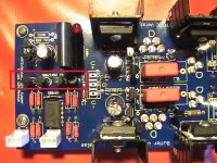
You will see 4 in a row,
that is where I placed the "Matched" set of 170's
on my Blue Board.
I just guessed I may be wrong,
I ask the same question and receive the same useless
answer as you just received to look at post 4,
Looking at post 4 is the same as looking at the board in your hand.
Attachments
........
I ask the same question and receive the same useless
answer as you just received to look at post 4,
Looking at post 4 is the same as looking at the board in your hand.
wow, I caught that in a glance before I even had the boards. way to ingratiate yourself to those who might help you if something goes wrong

For what its worth, I think these boards are very well designed and Salas, Tea-Bag and others have been VERY helpful and open with their time. The boards are also dirt cheap, imho compared to what you would have to spend on a retail product.
The picture of the schematic, board and solder screen with grounding layout is very useful. The BOM on the 1st page of this thread complements the board perfectly with little doubt, imho. If there are doubts, then post a question, but be nice about it. Insulting the original designer(s) gets you nowhere.
Anand.
You will see 4 in a row,
that is where I placed the "Matched" set of 170's
on my Blue Board.
I just guessed I may be wrong,
I ask the same question and receive the same useless
answer as you just received to look at post 4,
Looking at post 4 is the same as looking at the board in your hand.
We are here to learn ...i think, you owe it to yourself to read the thread, especially post 77, then thank Salas et all and be happy you got a whole lot for nothing....and by the way post 4 has an Example which profusely explains things....look closer...find the link....

Last edited:
Set up your test bench. Put one diode on it. Wait a pair of minutes for it to stabilizy. Take a look at the DMM. Slightly heat it with a lighter for a short time, like half a second. Take a look at the DMM again. Surprise!When measuring, they took some time to stabilise, and even then I am not convinced that they did stabilise fully - they measured slightly differently the next day. Normal? I don't know. They're Panasonic, but it seems they make some slightly crap stuff too.
Maybe not a voltage reference as stable as we though
The same happens to the 2SK170 when testing them.And they don't need to bee too closely matched, only to have a close idss. How much, I don't know.
DMM may have a thermal variance as well. I don't know too much about the inside part of a DMM, but I suppose that they (at least the good ones) must have any kind of stibilizer for that. Otherwise we wouldn't trust them in such a godly way.
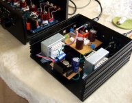
ppcblaster, yours is the first board of the final blue production that I've seen with all the components
P2p wiring is very fun, like some kind of hability and cleverness game. Definitly much more fun than stuffing a board with the marked components in the marked places
In my last gainclone finished, everyting is made point to point except the psu. Since it is regulated, it doesn't need big capacitors. Just get a higher supply voltage and drop enough on the regulators to not suffer any voltage dropping in the output while high peaks.
Last edited:
Set up your test bench. Put one diode on it. Wait a pair of minutes for it to stabilizy. Take a look at the DMM. Slightly heat it with a lighter for a short time, like half a second. Take a look at the DMM again. Surprise!
Maybe not a voltage reference as stable as we though
Exceeding the operating temperature range by heating with a lighter doesn't seem like a reasonable test of stability.
P2p wiring is very fun, like some kind of ability and cleverness game. Definitly much more fun than stuffing a board with the marked components in the marked places
P2p is fun, but it looks like **** when it's finished, even when you do it neatly, and if you can get the circuit to work, it's all the more kudos. Mine latest one doesn't work at all, and I haven't worked out why yet. I may have cooked a 2sk170 or a BC550C, and if so, I will never get to the bottom of it without rebuilding from scratch.
What in the hell made me imagine that rebuilding the whole circuit p2p would be quicker and more reliable than mending the PCB is beyond me. Doofus me!
Hi salas:
use +/- 20V DCin not too high voltage input?, because dcb1 just use +/- 10v DCin
mikeliu
use +/- 20V DCin not too high voltage input?, because dcb1 just use +/- 10v DCin
mikeliu
You can break the copper connections between + to + and - to - of blue's 4700uF pos and neg filter cap pairs and introduce a 39R 5W per rail between them underneath. With 8R2 5W set resistors where it says 10R 5W, will surely create an around +/-20VDC final DCin to the regs when using a 2x21VAC trafo. Use 35V caps, no less.
Who said that I've exceeded it?Exceeding the operating temperature range by heating with a lighter doesn't seem like a reasonable test of stability.
I though that in p2p constructions boards were not used. Are designs made on vector boards included as P2P builts? A saw them as a transition between PCBs and P2P
Hi salas:
so we choose +/- 15V AC output trafo right?
so we choose +/- 15V AC output trafo right?
You can break the copper connections between + to + and - to - of blue's 4700uF pos and neg filter cap pairs and introduce a 39R 5W per rail between them underneath. With 8R2 5W set resistors where it says 10R 5W, will surely create an around +/-20VDC final DCin to the regs when using a 2x21VAC trafo. Use 35V caps, no less.
Who said that I've exceeded it?
I though that in p2p constructions boards were not used. Are designs made on vector boards included as P2P builts? A saw them as a transition between PCBs and P2P
If you connect leg to leg I guess we can call them supported p2p?
I though that in p2p constructions boards were not used. Are designs made on vector boards included as P2P builts? A saw them as a transition between PCBs and P2P
I think it's p2p if you're not using veroboard, but a basic matrix of copper dots around a grid of holes. Even veroboard is p2p in my book. If most of your wiring is resistor legs, it's point to point for sure!
This shows there are a variety of opinions.I think it's p2p if you're not using veroboard, but a basic matrix of copper dots around a grid of holes. Even veroboard is p2p in my book. If most of your wiring is resistor legs, it's point to point for sure!
Last edited:
- Home
- Source & Line
- Analog Line Level
- Salas hotrodded blue DCB1 build