Thanks again Andrew, you’ve convinced me that such a set-up will sacrifice the fundamental benefits of balanced operation. Therefore I’m going to omit a volume pot altogether from this build and use it purely as a balanced buffer. I’ll be looking further upstream to incorporate a volume control.
Cheers
John
Cheers
John
just received my Hypnotize Boards in the post.
I have a +-12v SLA battery power supply with 20A on each rail available to the B1. I would like to know the best way to run my B1 with the Hot-Rod tweaks. Do I just need to swap out the 68R 1/4 watt resistors for 2 x 100R 5 watt wirewound in parallel and add beefier heatsinks to the TO247 transistors, or is there more I can do with a battery supply. I also have +-24V SLA availible as well, but guess that this may be a bit OTT.
any help would be much appreciated.
Brad
Use a transformer and run it off the mains. Its supplies are good enough so to safely avoid batteries. The Hypno has 47R or 10R marked positions on board. Use only the 10R fatter ones hotrod, enhance sinking.
*If you still want to run it off +/-12V batteries you will have to only populate the audio section beyond the +G- connector, skip the 7812, wire Con+ to NOTE, and feed power on that connector (see Xray PCB view, page 1). Cut out the left to +G- connector's pcb side to use as shunt regs in another project. Mind you +/-V differences between batteries as they discharge are going to enhance DC offset.
*If you still want to run it off +/-12V batteries you will have to only populate the audio section beyond the +G- connector, skip the 7812, wire Con+ to NOTE, and feed power on that connector (see Xray PCB view, page 1). Cut out the left to +G- connector's pcb side to use as shunt regs in another project. Mind you +/-V differences between batteries as they discharge are going to enhance DC offset.
can I not use the +and- shunt regulation on the SLA supplies for the B1?
Brad
Explain this further pls. If you mean feeding the regs off batteries, it takes +/-20V or over input, and the CCS is going to drain them rather fast. It will mostly provide a further clean up interface and steadier impedance maybe.
HI Salas,
here is a bit more background....
I have 4 x 12v 20Ah SLA batteries in series which are being used to power my TDA1541 based DAC. They are charged using a power balancing circuit which ensures that all of the batteries get a full charge without overcharging any that reach full charge early in the cycle. I have also experimented with powering my active crossovers from the batteries which is why I have a larger voltage range than the TDA chip requires.I will probably not use the batteries on the cross over as I could not hear any difference compared to mains power. I can use all 4 of the batteries to power the B1 and your shunt regulators, which would give approx +/-26v. What is the CCS drain when the B1 is set up with the Hot-Rod mods?
Brad
cheers Salas,
so If I was to feed my B1 with the +/- 26v from 4 x 20Ah series SLA batteries I should be able to get around 100 hours running time, between recharges.
Is this the best way forward, or is it worth adding any extra filtering LC networks on the battery supplies before your shunt regs?
Brad
so If I was to feed my B1 with the +/- 26v from 4 x 20Ah series SLA batteries I should be able to get around 100 hours running time, between recharges.
Is this the best way forward, or is it worth adding any extra filtering LC networks on the battery supplies before your shunt regs?
Brad
You would not need extra noise filtering since the batteries all quiet in general. Why up the input loop's impedance with LC etc, I see no reason. You are not going to need the rectifiers of course, the local filter caps could stay for termination. Keep in mind that each input Mosfet is going to dissipate 3.2W with 26V input and each output Mosfet 2W for 0.2A setting. Just mount them pins under PCB and bolt their cases to the enclosure's floor with insulator pads in between.
cheers Salas,
I have just got to decide if this is the best way forward. I can run my DAC, and I guess it would be the same for the B1, when charging the batteries, but I am not sure if the 3-4 day drain cycle would be workable. Obviously I can extend this a little by turning the B1 off which I would probably do as well.....
might be best to do the build with a nice EI core transformer and go from there. At least I would be taking advantage of my balanced AC power supply.
Brad
Hi Salas,
thank-you for the help and advice. I am now going to build 2xDB1s, both using an AC supply. 1 of the DB1s will use this voltage module from Tent labs with Texas Components TX2575 resistors throughout.
Volume control
I am also planning on using 4 x TX2575s @ 220R and 2 x TX2352s @220k in the DB1.
I have not decided on a volume control for the other DB1, but will most likely try out one of the Lightspeed variants, if i can find one with decent remote control and source switching.
Brad
Hello,
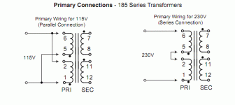
I've assembled the board and ready to test it. Unfortunatelly, I have problems sourcing the transformer localy. Lower or higher voltages are available only. How high is high? 2x17V still acceptable? Is there a way to test it without a transformer? Walwart? Batteries?
Thank you in advance.
I've assembled the board and ready to test it. Unfortunatelly, I have problems sourcing the transformer localy. Lower or higher voltages are available only. How high is high? 2x17V still acceptable? Is there a way to test it without a transformer? Walwart? Batteries?
Thank you in advance.
I guess, I should have patience an order this one then.
MULTICOMP|MCTA050/15|TRANSFORMER, 50VA, 2 X 15V | Farnell United Kingdom
Salas, what are your thoughts on it?
MULTICOMP|MCTA050/15|TRANSFORMER, 50VA, 2 X 15V | Farnell United Kingdom
Salas, what are your thoughts on it?
- Home
- Source & Line
- Analog Line Level
- Salas hotrodded blue DCB1 build