The DCB1 has low output offset.
How much is it per channel hot?
nash
I suppose that If the DCB1 is putting out a few mV positive, and the UA2192 is putting out a few mV positive, that I could lower the combined output by swapping the jfets in the DCB1, so that its DC output might become negative?
When swapping for negative offset, that move also modifies the THD harmonic profile towards less second without lessening the third. The more closely matched the more perfect the cancellation.
Up to 5mV offset is generally acceptable. What I saw about THD profile and offset polarity was in a perfectly symmetrical PSU rails breadboard experiment of increasingly different IDSS pairs from nearest match to 1.35mA dif and swaps. Maybe its not exactly replicated in a build with slightly different rails but its a trend I informed you about since you were interested in swaps towards offset cancelling with other gear in the chain.
In your QuantAsylum first picture the second harmonic to third harmonic relation is as expected (post#5865). You can use that analyzer at preferably 1VRMS for assessing anything you change in the build. By the way did you try rotating the transformer or connecting the box to signal ground for maybe killing some hum related spikes there?
In your QuantAsylum first picture the second harmonic to third harmonic relation is as expected (post#5865). You can use that analyzer at preferably 1VRMS for assessing anything you change in the build. By the way did you try rotating the transformer or connecting the box to signal ground for maybe killing some hum related spikes there?
Something happen er I can't explain. I misconnected a benchmark dac1, using XLR to RCA with pin 3 to shield. At the time , the DAC had stopped working on on the bench. To verify, I hooked it up to the dcb1 with same XLR to rca cable. little to no output. Only very low level could be heard in on full dcb1 volume output.
Next day, DAC is working fine. Hooked up to dcb1 and signal passes when power is off. Input hot to output hot measured about 8k with dcb1 off.
Seems like jfets and relay are shorted . I did not hear speaker protection switch on at any time. DAC to amp using variable RCA outs is fine.
Next day, DAC is working fine. Hooked up to dcb1 and signal passes when power is off. Input hot to output hot measured about 8k with dcb1 off.
Seems like jfets and relay are shorted . I did not hear speaker protection switch on at any time. DAC to amp using variable RCA outs is fine.
I just wanted to write this down somewhere, as I will be away for a couple days.
I removed the jfets. They pass the gate/source and gate/drain test on diode test setting of DMM. Resistance from drain to source is around 38 to 50 ohms each pair with gate floating.
Right now, the jfets are out and board disconnected from the volume control/output rcas. This DCB1 uses a 10 Ohm resistor, diode bridge and ceramic cap to lift audio ground from safety earth. This is also not connected and the mains transformer is disconnected. It's just the PCB with the JFETS out.
All measurements are taken at the PCB input/output connectors.
1) The input ground is shorted to the Left/Right/ground of the output connector. ( I assume this is the correct normally closed output relay state. )
2) Resistance of 220k between signal input and output pins on each channel.
3) Resistance between input L/R signal pins show 440 KOhm.
I have been turning the unit on/off a lot recently with the volume down while leaving the amp running. I think the low volume reported earlier was due to forgetting to turn the DCB1 on.
However, with DCB1 off I was surprised to hear music at a reasonable listening level.
To measure Idss, I used a plug board.
D in row 1, G row2 , S Row 3, all column 5. 470 ohm resistor plugged into col 4, row3. Jumper connecting row 2 and 3 to ensure Vgs is zero. Meter reading DC volts across resistor. 10 VDC power supply hot to column 3 row1. PS return to free side of resistor.
3.8 V across 470 ohm is about 8ma.
D in row 1, G row2 , S Row 3, all column 5. 470 ohm resistor plugged into col 4, row3. Jumper connecting row 2 and 3 to ensure Vgs is zero. Meter reading DC volts across resistor. 10 VDC power supply hot to column 3 row1. PS return to free side of resistor.
3.8 V across 470 ohm is about 8ma.
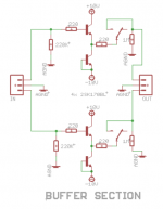
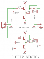
There were two output relay connection arrangements in Hypnotize. The first one or two batches used no connection during rest (power off) and further batches used ground connection. Here are both gen buffer section schematics. You can use them to verify if your relay function is in correct working order.
Attachments
Thanks Salas!
If I read the diagram right, there should be a dead short between output signal and ground with power off and 1M with power on when jfets are out.
I will recheck the results with the power on and the jfets out on one channel. That will verify one channel in the relay.
If I read the diagram right, there should be a dead short between output signal and ground with power off and 1M with power on when jfets are out.
I will recheck the results with the power on and the jfets out on one channel. That will verify one channel in the relay.
Last edited:
I have two questions then:
There is an added green trace between the 220R and AGND in version 2. In version one, the output from the jfets is connected to either the output pin or is left floating.
In version two, the output from the jfets is connected to the output pin when the power is either on or off, and is also connected to ground when the power is off, effectively shorting the input to the power amp.
Is this why you can turn off the DCB1 before the amp?
2) In the shunt schematics, the grounds are not labelled AGND. The buffer and relay grounds are labelled AGND.
Is the intent for the second ground termination (AGND?) nearest the jfets to be separated from the Shunt ground with a ground loop isolator?
Then is it correct if the shunt grounds go directly to the Power supply center tap (Zero volt line) and safety earth, while the AGND passes through a ground loop isolator then to the zero volt line....
Is the 1M resistor necessary?
When the unit is off and jfets out, I measure 0 ohm with probes on either side of the 1M resistor. That corresponds to the second drawing. When the relay is energized, the
- Home
- Source & Line
- Analog Line Level
- Salas hotrodded blue DCB1 build