I fitted parallel outputs although i mostly use one set, what is the benefit of fitting 100R resistors and how should they be connected?
Cheers
General good practice. Not always much necessary. But it can help in some weird cases. Its to damp the extra cable's capacitance. For signal integrity and current limiting. Put in line with output RCA hot.
A line level of 2.1Vac is roughly 3Vpk
Feeding that to a 10k Rin of a Receiver will result in a peak current of 300uA into the resistance.
To that you should add on the capacitance charging current. Allow ~1mApk
The total transient output current is thus <=1.3mApk
A 100r output resistor to help add stability to the Buffer stage will drop <130mVpk
This is a loss of output of less than 0.4dB and most of that is due to the capacitance of the cable and any RF attenuation in the Receiver.
If capacitance is low the signal lost through the 100r is only 0.1dB.
That's why we can afford to place a stabilising resistor on the output of line level stages.
If the Rin, or Zin, of the Receiver is very low, then the load stabilising resistor will lose more of the wanted signal. Take the example of a Power Amplifier driving an 8ohms speaker. To minimise the signal lost in an output stabilising resistor we add a parallel inductor to pass the audio signal.
Fortunately we don't need that complexity for Line Level stages.
Driving a low impedance headphone probably does get some benefit from using a Thiele Network on the output but for some reason it is rarely adopted by Builders.
Last edited:
Thanks Andrew. I did wonder if for example when driving four identical power amps there would be a noticeable reduction in output from the two fed via the resistors but loss of less than 0.4dB is not really worth bothering about. I might even fit carbon types to see what (if any) difference they make.
Either if the groups of fives are backwards or if some in them are dead by soldering heat are the first things to check. Follow the D symbol on PCB for its flat side imeans cathode.
Thanks. I actually figure it out already. I was mislead by square soldering pad, which I thought is cathode always, but it is not. Now everything works fine.

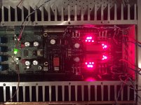
I know now. A lot of backbreaking fiddleling. 228 mA negative and 278 mA positive with 5R6 resistors. Dancing on around half a mV negative offset on both left and right under warmup.
I also had to throw in a wire between PSU cap zero and delay section since I noticed I had sawed off its return feed to get room for the board.
I also had to throw in a wire between PSU cap zero and delay section since I noticed I had sawed off its return feed to get room for the board.
Attachments
Genuine or not?
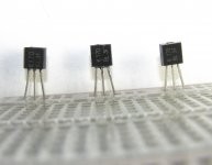
May I have some confirmation if the K170 on the right is genuine, or not? The one on the left is genuine (from tea-bag), the middle is confirmed fake by Salas. IDss is within a reasonable range 8-11ma out of 10 tested. Vgs is usually around -.8 out of the 10 i tested.
The font, crease at the top, and measurements make me question it. Im not sure if the package was ever altered during its lifetime of the product. cant hurt to ask, right?
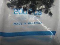
I also have a pic of the bulk packaging.
regards")
May I have some confirmation if the K170 on the right is genuine, or not? The one on the left is genuine (from tea-bag), the middle is confirmed fake by Salas. IDss is within a reasonable range 8-11ma out of 10 tested. Vgs is usually around -.8 out of the 10 i tested.
The font, crease at the top, and measurements make me question it. Im not sure if the package was ever altered during its lifetime of the product. cant hurt to ask, right?
I also have a pic of the bulk packaging.
regards
Attachments
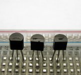
The one on the right looks suspicious to me. Notice how the "3" doesn't look the same as the original.
Did you get them from some seller in China?
I learned a while back to only buy these from reliable sources.
Jim's Audio was the only Asian seller I found that sold authentic K170/J74s.
Did you get them from some seller in China?
I learned a while back to only buy these from reliable sources.
Jim's Audio was the only Asian seller I found that sold authentic K170/J74s.
I did buy from a reliable seller. I put two small orders of 20 in, those two orders came back with genuine fets. That's when I tried for the bigger order. The company has been responsive, I just want to be 100% sure.
I tested 10 of the ones on the right. Idss is between 8-11ma, Vgs is around -.8mv. I have tested the pinch off voltage, I'll do that tonight.
I tested 10 of the ones on the right. Idss is between 8-11ma, Vgs is around -.8mv. I have tested the pinch off voltage, I'll do that tonight.
If you measured Idss then Vgs must be zero mVdc. That is the definition of Idss.I did buy from a reliable seller. I put two small orders of 20 in, those two orders came back with genuine fets. That's when I tried for the bigger order. The company has been responsive, I just want to be 100% sure.
I tested 10 of the ones on the right. Idss is between 8-11ma, Vgs is around -.8mv. I have tested the pinch off voltage, I'll do that tonight.
If you want to measure Vpinchoff then the easiest way is to follow Borbely. The jig is simple. The method is simple. The required equipment is simple.
- Home
- Source & Line
- Analog Line Level
- Salas hotrodded blue DCB1 build