Congrats for succesfull dcb1, you're in prefect path for those AlephJWell fantastic! Thanks Salas, Andrew T for all the help, I shall finish the build up and enjoy the music
Special thanks to Teabag for being being a proper gentleman and sending irfp240/9240s and the reg two years after I bought the kit (I discovered these were missing on finally opening it).
Now for the Aleph J")
your welcome, and this pic is badaxx do you mind if I add it to my blog collection?
No need to ask, that's a massive compliment thanks, not even finished! I've got the LDR ready to go in but I'm getting used to the pot at the mo, bit of a cliché but music has taken on a new life, I've never heard it so good.
i justed used the search function, but i am afraid looking for posts with "green" or something similar does not give me the information i was looking for, so may i ask another question.
In the kit i ordered from T-bag (thanks!!) i got green and red leds. Due to Salas comment (#5178) i should use the green ones for the triplets to get the expected 600mA using 3R3 resistors, right? Or do i have to mix it up?
Thanks a lot!
In the kit i ordered from T-bag (thanks!!) i got green and red leds. Due to Salas comment (#5178) i should use the green ones for the triplets to get the expected 600mA using 3R3 resistors, right? Or do i have to mix it up?
Thanks a lot!
some green LEDs have a higher Vf than some red LEDs.
But many are of very similar voltage.
Low brightness red LEDs generally have a lower Vf.
You can mix up different Vf to try to achieve a particular Reference voltage.
The CCS in the Salas Shunt Regulator does not need a particularly accurate reference voltage. One can trim the resistor value to achieve the current value you have chosen.
eg. using three LEDs giving 5.5V to apply across the mosFET Vgs + resistor leaves very approximately 2V across the resistor.
Using 3 off 10r across that voltage gives a current through each resistor of ~200mA for a total of ~600mA. (the same 2V across a 3r3 gives 606mA, the next step up to 3r6 gives 555mA, or down to 2r7 gives 740mA).
If after building you find that the current is not what you wanted, you can change one, or more, of the 10r to 11r, or to 12r, or add a 4th resistor. This trimming is very easy if you plan for it. i.e. tack on the resistors rather than insert them through the holes.
The early DCB1 had multiple pads/holes for multiple parallel resistors. A great idea ! (I generally fitted 4 resistors) Shame some PCBs did not copy this feature.
Last edited:
aaaah, ok, now i understand this part of the schematics... 2nd law of Kirchhoff and using a constant voltage drop over the leds! Thanks!
So, by using different leds i might increase the reference value and so for a constant resistor due to Ohms law the current would be higher than compared with a lower reference voltage (now the info of the kits from tea-bag that a green triplet leads to a higher current is clear!).
Still, increasing the current, if it is not as expected, is easier done by changing the value of the resistor by adding parallel ones.
Thanks a lot!
Hey! So after soldering all the parts i came to the first test -> the 5led rails did not light up. after some measuring and looking into the schematics... ok, the leds were in the wrong direction, for some reasons the position of the kathode and squared solder pad differs to those from the 3led rail! My fault
After changing the direction -> one side was ok, at least! Again some measuring showed me that i destroyed some of the leds...
long story, bud in the end i used green leds for the triplets to get some red ones to replace the destroyed les!
it works now!!!
Some measurements:
V+ = 9.71V
V- = -9.77
Offset:
R: -1.8mV
L: 0.1mV
Voltage drop along R1:
IRFp240 side: 1815mV
IRFp9240 side: 1890mV
At the moment i look if it is stable and check the heat. The fets do not get that warm, can touch everything easily but my resistors (3R3 5W KIWAME) get reaaally hot. i can touch them about 4 seconds...
So, is this a problem? and can i decrease the offset or should i be happy with the results?
Thanks!
the 5led rails did not light up. after some measuring and looking into the schematics... ok, the leds were in the wrong direction, for some reasons the position of the kathode and squared solder pad differs to those from the 3led rail! My fault After changing the direction ->
one side was ok, at least! Again some measuring showed me that i destroyed some of the leds...long story, bud in the end i used green leds for the triplets to get some red ones to replace the destroyed les!
it works now!!!
Some measurements:
V+ = 9.71V
V- = -9.77
Offset:
R: -1.8mV
L: 0.1mV
Voltage drop along R1:
IRFp240 side: 1815mV
IRFp9240 side: 1890mV
At the moment i look if it is stable and check the heat. The fets do not get that warm, can touch everything easily but my resistors (3R3 5W KIWAME) get reaaally hot. i can touch them about 4 seconds...
So, is this a problem? and can i decrease the offset or should i be happy with the results?
Thanks!
That's why my example shows three resistors and why my Mez build uses 4 resistors.................... but my resistors (3R3 5W KIWAME) get reaaally hot. i can touch them about 4 seconds...
So, is this a problem? and can i decrease the offset or should i be happy with the results?
Thanks!
it works now!!!
Some measurements:
V+ = 9.71V
V- = -9.77
Offset:
R: -1.8mV
L: 0.1mV
Voltage drop along R1:
IRFp240 side: 1815mV
IRFp9240 side: 1890mV
At the moment i look if it is stable and check the heat. The fets do not get that warm, can touch everything easily but my resistors (3R3 5W KIWAME) get reaaally hot. i can touch them about 4 seconds...
So, is this a problem? and can i decrease the offset or should i be happy with the results?
Thanks!
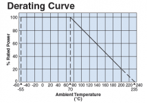
Your offset is not objectionable at all. Kiwame is made by OEM. The original part is KOA SPR. Its a +/-350ppm carbon film type, 100% nominal power rated up to 70C ambient. I.e. its well in thermal spec the way you use it at about 1W dissipation and in moderate ambient. Nice proven part although a very low ppm film or wire wound type would be potentially superior.
Attachments
one rail stopped working after one year
Hi all,
after more then 1 year of (happy) listening, my board has begin to make strange things:
at beginning (2 weeks ago) the 5LED group on V- rail was ON at power on and after a while they went off (actually all V- rail went off) and sometimes went on again without any appearent reason...
nowdays the 5LED NEVER light on and so all the V- rail (V- = -22v)
I'm sure the 5LED are ok becouse they still light up (for fews seconds) when I power off the board.
the V+ rail is ok (V+ = +10v) it is working at moment BUT yesterday for the first time the problem started ALSO on this side of the board
can someone please tell me what to check to know which component has to be replaced?
tnks'
Saverio
Check soldering around the Mosfets and the Mosfets themselves. Also the two JFETs near the 1 Ohm/10 Ohm resistors.
one of the IRFP240 is dead...
in case I can't find IRPF240 from local resellers (in Rome not so easy) the BOM says IRPF140 should be ok... do I need also to substitue IRPF9240 with IRPF9140?
I have a 100K stereo stepped attenuator. I would like to use it between my source (cd player) and the Hypnotize, which has significantly transformed my system.
Will this lead to an impedance matching imbalance? What component changes on the B1 need to be made?
Thanks for your help.
Will this lead to an impedance matching imbalance? What component changes on the B1 need to be made?
Thanks for your help.
If meaning the dcb1 in any form, although a 100k pot is not preferred as a value but maybe the specific one has great build quality and wants it to be tried, then 1Meg resistors instead of the 220K input to ground ones should be used. They are there to ensure no DC will come out if a wiper or a stepped contact loses touch because of wear with use. Since they parallel the pot they should be at least 10 times higher than its value.
once i had a very nice tkd 100k 2P65CS, but instead of making extra issue for dcb1, i sold that attenuator to my friend for his tube preamp and buy tkd carbon 25k and alps blackbeauty 10k, and still have extra cash
I'd rather use proper potentiometer value as Salas suggested, 25k if i remember correctly, where 10k is still good
I'd rather use proper potentiometer value as Salas suggested, 25k if i remember correctly, where 10k is still good
Thanks for your replies. Apologies for the ambiguity B1 - DCB1. I have the Hypnotize so it's a DCB1.
I'll try the 100K volume pot with the 1M resistors across the DCB1 input and see how it sounds. Maybe l'll buy a 20 or 15K stepped volume pot that goes with the original design parameters of the DCB1.
I'll try the 100K volume pot with the 1M resistors across the DCB1 input and see how it sounds. Maybe l'll buy a 20 or 15K stepped volume pot that goes with the original design parameters of the DCB1.
May I ask for a recommendation please? Im sure I'll have a ton of questions in the near future, but I'll start with one right now. I'm building a two board dcb1 and I'm having trouble sourcing the transformer. I've read that it should be 100va 15v-0-15v x2. I'm having trouble finding that spec. Should I use two transformers, or just the one? Any help would be appreciated, thanks! I also don't mind spending for quality
- Home
- Source & Line
- Analog Line Level
- Salas hotrodded blue DCB1 build