Measure the temperature on those nearby electrolytics first. There is a rule of thumb to derive their useful life from their ratings. Each 10C less than the max specified doubles their life expectancy. I.e. If there is a 1000 hours 85C spec it translates to 16000 hours at 45C. Resistors with ceramic back don't need isolation and simple continuity check from back to their leads will confirm.
I will measure everything tonight thanks Salas.
P.S. If the case temperature of the capacitors seems good for expected lifetime, better avoid resistor links as they add some little inductance.
Im glad you said that, i didnt fancy stripping it down again! i will see if i can get a little sheet of ally behind the resistors to do a bit of sinking.
Measure the temperature on those nearby electrolytics first. There is a rule of thumb to derive their useful life from their ratings. Each 10C less than the max specified doubles their life expectancy. I.e. If there is a 1000 hours 85C spec it translates to 16000 hours at 45C. Resistors with ceramic back don't need isolation and simple continuity check from back to their leads will confirm.
The resistors are 63C, caps are 52, so shouldnt be any premature failure.

Heat sink?
Hey everyone!
First of all, thanks a lot for this wonderful project! I am really looking forward in building this buffer and finally after finishing my diploma thesis i hope to find some time to do that!
At the moment i am wondering how i should mount my transistors on my heat sink. I am going to build the 600mA version so for that i bought a 0.9K/W heat sink. In a post in this thread it is mentioned that the big electrolytic capacitors (4700uF) should not get to warm to increase their life span.
At the moment i have three different ideas.
1. I use an aluminium L-profile which leads the heat from the mounted IC's to the heat sink. By that the heat sinks are not so close to the capacitors. (first picture left side)
2: I place the heat sink very close to the pcb, by that i don't need the aluminium profile but the heat sink is quite close to the capacitors. (first picture right side)
3: Same as the second version but the heat sink is moved a little bit so that there is more space for the input/output. (second picture)


I would prefer version three, but i am not sure if that will be a problem.
I hope someone can help me! Thanks a lot!
Philip
Hey everyone!
First of all, thanks a lot for this wonderful project! I am really looking forward in building this buffer and finally after finishing my diploma thesis i hope to find some time to do that!
At the moment i am wondering how i should mount my transistors on my heat sink. I am going to build the 600mA version so for that i bought a 0.9K/W heat sink. In a post in this thread it is mentioned that the big electrolytic capacitors (4700uF) should not get to warm to increase their life span.
At the moment i have three different ideas.
1. I use an aluminium L-profile which leads the heat from the mounted IC's to the heat sink. By that the heat sinks are not so close to the capacitors. (first picture left side)
2: I place the heat sink very close to the pcb, by that i don't need the aluminium profile but the heat sink is quite close to the capacitors. (first picture right side)
3: Same as the second version but the heat sink is moved a little bit so that there is more space for the input/output. (second picture)
I would prefer version three, but i am not sure if that will be a problem.
I hope someone can help me! Thanks a lot!
Philip
Replaced the faulty pair of SK170BLs in the quadruple and DC offset is completely vanished. Happy
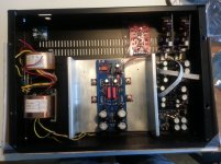
Working on enclosure lay out:
Congrats. Let us know when you finish.
Phil,
the L bracket should not be down at the bottom of the sink for good dissipation.
Move it up.
You can place the edge of the PCB just under the L and mount the transistor from the top side.
This allows you to raise the L a bit higher than using a bottom mounting transistor.
You also get betting cooling if the transistor is close to the vertical face. But be sure the inside of the angle is flat where the transistor mounts. The outside of the angle can be made flat.
Hey Andrew!
I plan to use 2cm bolt spacer for the pcb (so not 1cm as in the pictures) and lift the L about 5 mm, i hope thats enough space below.
What do you mean by
I plan to use 2cm bolt spacer for the pcb (so not 1cm as in the pictures) and lift the L about 5 mm, i hope thats enough space below.
What do you mean by
That there are no scratches on the L brackets? I will be careful and use a heat conductive film for the transistors and a paste for the heatsink/L bracket connection. The space between the transistor and the vertical face is also around 5mm.But be sure the inside of the angle is flat where the transistor mounts.
I have completed my DCB1 board and it works and passes signal quite beautifully.
The irfp240 and irfp9240 appear not to get warm at all. I expected some heat as I currently have ccs at 200ma. They are bolted to the case at present.
I assumed that if the devices were not working the buffet wouldn't pass signal. Would I be correct?
Can I verify ccs of 200ma at idle by measuring?
The irfp240 and irfp9240 appear not to get warm at all. I expected some heat as I currently have ccs at 200ma. They are bolted to the case at present.
I assumed that if the devices were not working the buffet wouldn't pass signal. Would I be correct?
Can I verify ccs of 200ma at idle by measuring?
Some measurements
V+ at test point 9.76v
V- at test point -9.81v
Voltage across R1 +ve rail 1.67v
Voltage across R1 -ve rail 1.58v
DC mv at output reads -0.7mv on left channel and -3.5mv on right channel.
Do these look ok? I am a little concerned that the irfp240/9240 are functioning correctly. I should state that I had initially installed every LED backwards.
They do function correctly, running 167mA & 158mA as proved by your Rset voltage drops. They are just chosen to can serve a very long life even in heavy hot rod conditions. At around 200mA they are always lukewarm or even cold when the sinking is king size. You can either use more current or leave it at that just knowing that the thermal reliability of your build is awesome.
Well fantastic! Thanks Salas, Andrew T for all the help, I shall finish the build up and enjoy the music
Special thanks to Teabag for being being a proper gentleman and sending irfp240/9240s and the reg two years after I bought the kit (I discovered these were missing on finally opening it).
Now for the Aleph J
Special thanks to Teabag for being being a proper gentleman and sending irfp240/9240s and the reg two years after I bought the kit (I discovered these were missing on finally opening it).
Now for the Aleph J
The inside edges of an angle are usually not exactly flat and some have a very pronounced radius in the "V".Hey Andrew!
I plan to use 2cm bolt spacer for the pcb (so not 1cm as in the pictures) and lift the L about 5 mm, i hope thats enough space below.
What do you mean by
That there are no scratches on the L brackets? I will be careful and use a heat conductive film for the transistors and a paste for the heatsink/L bracket connection. The space between the transistor and the vertical face is also around 5mm.
You need to check with a straight edge held up to the light if the area you intend to clamp onto is actually flat.
The outside edges are more likely to be flat and if not can be made flat with some machining/grinding.
Just wanted to thank Salas and TeaBag, specially Teabag for sending me some more transistors F.O.C. Excellent
your welcome, and this pic is badaxx do you mind if I add it to my blog collection?
After some drilling work and cutting some threads I saw your post andrew and decided to use a third screw in the middle to press the L-brackets onto the heat sinks... So after a second try and some fun with the heat paste i assembled all together and i think its quite nice now! I hope heat is no problem in the future, also for even for more current (?).
By they way, if i want to hotrod one step further, so 1A version, how many VA should my toroidal have? At the moment i got a 120VA 2x15V, but i am not sure if thats enough for the 1A version. Anyway, i will start with the 600mA version first... (and will check the thread for more information about the 1A version...)
Here some pictures, maybe someone can use them in the future


By they way, if i want to hotrod one step further, so 1A version, how many VA should my toroidal have? At the moment i got a 120VA 2x15V, but i am not sure if thats enough for the 1A version. Anyway, i will start with the 600mA version first... (and will check the thread for more information about the 1A version
...)Here some pictures, maybe someone can use them in the future
- Home
- Source & Line
- Analog Line Level
- Salas hotrodded blue DCB1 build