Ooops! Pull and check the audio signal path JFETS quartet for matched IDSS or even a dead one
Salas Hello, hello to all.
I tried the four FET with one of these contraptions
M328 LCR-T4 MOSFET Transistor Test Diode Triode Capacitor ESR 12864 LCD Display | eBay
and it seems they all work.
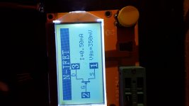
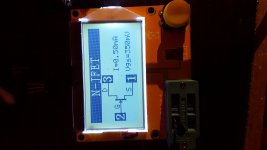
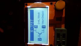
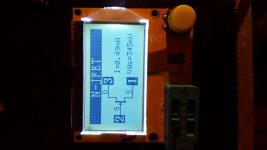
I also checked the mosfet and even those seem to work.
Bearing in mind that the Vout be corrected is on the right channel output what else can I check / replace?
Thank you
You need to know the IDSS of those four JFETS and how they are pairing for matching. Use a 9V battery and a 100 Ohm resistor. Connect the resistor between drain and bat +. Connect gate and source to bat -. Measure voltage drop across the resistor for each JFET and convert to mA IDSS with Ohm's law.
Merry Christmas everyone !
Looks nice and slim congratulations.
A corresponding question, is it possible to use chassis as heatsink for the Salas Hot rod at 18vac trafo - 25 VDC on the rectifier.
I am thinking in between the Amp like chassis and the small one.
Or which kind of metal plate can be used to put inside the sleek chassis to act as a heatsink ?
Here's my hot rod DCB1 in milled chassis.It only gets lukewarm now.
Thanks to NP and Salas for this amazing preamp!
Looks nice and slim congratulations.
A corresponding question, is it possible to use chassis as heatsink for the Salas Hot rod at 18vac trafo - 25 VDC on the rectifier.
I am thinking in between the Amp like chassis and the small one.
Or which kind of metal plate can be used to put inside the sleek chassis to act as a heatsink ?
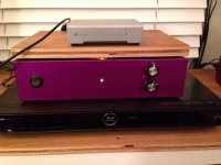
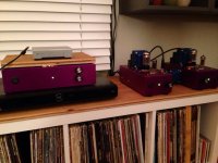
Well, here it is. Removal of wrong relays went great. NEC relay install went great. Currently configured for three input. I wired a second set of series rca's so I can run my head amp without changing rca's. Sorry about the schiit I put on top of your preamp Salas. Thanks for all the help. Very pleased with the sound. Definitely adds clarity and increases three dimensionality. The top end is noticeably more sparkly and the bass is more present without being bloated. Magical. Thanks all
Sent from my iPhone using Tapatalk
Here's my hot rod DCB1 in milled chassis.It only gets lukewarm now.
Thanks to NP and Salas for this amazing preamp!
Very nice!
Nice, it was down to those lookalike relays of course. The devil's in the details as always. What method you used to rework for exchanging the relays? That would interest some members.
Happy that we nailed the issue and you even like the sonics.
Salas, I ended up using lots of solder wick and solder plunger. Didn't end up needing to use a desoldering iron per se but the old relays got pretty trashed in the process. But I took my time so as not to pull out any solder pads or ruin any traces. Worked like a charm. Mostly just took my time.
I have it between my sources and my diy 6v6 monoblock tube amps. Really pleased. Thanks again!
Corey
Merry Christmas everyone !
Looks nice and slim congratulations.
A corresponding question, is it possible to use chassis as heatsink for the Salas Hot rod at 18vac trafo - 25 VDC on the rectifier.
I am thinking in between the Amp like chassis and the small one.
Or which kind of metal plate can be used to put inside the sleek chassis to act as a heatsink ?
3mm ALU plate bottom will only feel lukewarm at 200mA
what are the problems if we use it as power to the soekris dac? since the impedance curve increases after 100kHz from the shunt is it recommended? I see few are using to power the soekris dac. But what about the impedance at higher frequencies where the dac will work so just a bypass cap near FPGA or shift register would help? Or we can just use the dcb1 blue and there wont be any issues?
I don't know details I only know that a guy has shown a DCB1 Hypnotize as power supply and buffer for the Soekris once here raving about that combination. The rise for just 170mA spare will be 3.5mOhm at 100kHz and 34mOhm at 1MHZ when the pass band is typically below 1 mOhm by the way. But cabling alone should have inductance effects too anyway.
Yes indeed, I had advised for 470uF/35V good quality electrolytics instead of the plastic red capacitors in the PCB's middle for better 1/F (low to subsonic) noise filtering when used for digital. Clocks etc tend to be more sensitive in that area. There are pads for such capacitors there already.
Heat sink overload
Hi, I have eventually powered up my DCB1, many thanks to Salas and Tea Bag! I havnt played any music through it yet but from the readings I think its ok but I may have over done the sinks, ive got 2.5ohm ccs and the fets run at around 35 degrees. offset is .2 and 4mv is this a big difference? I have 1.2 and 1.3 volts across the ccs resistors. heres a couple of pics.
 [/URL][/IMG]
 [/URL][/IMG]
Sorry i couldnt work out how to make the pics smaller.
Hi, I have eventually powered up my DCB1, many thanks to Salas and Tea Bag! I havnt played any music through it yet but from the readings I think its ok but I may have over done the sinks, ive got 2.5ohm ccs and the fets run at around 35 degrees. offset is .2 and 4mv is this a big difference? I have 1.2 and 1.3 volts across the ccs resistors. heres a couple of pics.


Sorry i couldnt work out how to make the pics smaller.
0.2mV of output offset is good................. offset is .2 and 4mv is this a big difference? ..................
4mV is poor.
It depends on how your next stage processes that offset.
Hi, I have eventually powered up my DCB1, many thanks to Salas and Tea Bag! I havnt played any music through it yet but from the readings I think its ok but I may have over done the sinks, ive got 2.5ohm ccs and the fets run at around 35 degrees. offset is .2 and 4mv is this a big difference? I have 1.2 and 1.3 volts across the ccs resistors. heres a couple of pics.
The sinks maybe big but it looks good and having low temperature is always long term good. 4mV can be passable it just depends on the power amp if its high gain and DC coupled it may multiply the final mV more than you like or not.
P.S. Now you run about 0.5A CCS which is plenty but such sinks could sustain 1 Ohm setting resistors even. Maybe a future experiment. Cleanly put together until this construction stage BTW. Congrats.
Many thanks Salas. Im a bit disappointed with the offset on the left channel, I was really careful to put the matched fets in the correct order and I dont have a record of their measurements. My amps are AudioSector 3875s so im DC coupled. I forgot to say the voltage was exactly 10v either side when I first powered it up, 60va 15 0 15, its dropped a bit now to 9.96 both sides, Im happy with this as its within spec. Ive just got home from work and fired it up again, the offset has gone up a fraction on the right channel on start up to 1.2mv then it settles down, the left starts up on about 3.6 and settles at 4mv, one thing I have just noticed is the left channel is -4mv, is there any significance to this?
Last edited:
Its about the idss order i.e. the top one to have bit more than the bottom one in the schematic. Which is the most natural order and gives (-) offset. But polarity is only academic in this close matching context, no practical consequence. Sometimes swapping places in the higher offset pair makes it less or you just try a new even tighter matched pair. Below 5mV offset (either polarity) is within spec nonetheless.
- Home
- Source & Line
- Analog Line Level
- Salas hotrodded blue DCB1 build
 enjoy
enjoy