Hi Salas thank you!
The values on the current setting Resistors is 17 left side and 19 right side I have 10 ohm resistors
Sent from my ONE A2003 using Tapatalk
What do you mean 17 & 19? Volts DC on their inputs in respect to ground? If you measure each resistor leg to leg do they show 1.5V-2V drop each? That would be OK. Also did you measure DC offset mV across each audio output? Up to 5mV is a pass.
Hi Salas, apologize for not being specific.
Just got around this
I was measuring the values on resistors only. Will need to modify the probe to measure the values between rectifier legs and ground and Andrew suggested
The voltage drop on the resistors was measured in 2000m range so actually my values should be
1788 mv and 1900 mv which should be under 2v
Remaining checks
1. Measure the voltage drop on output resistors is less than 2v done
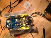
2. Message the DC Voltage between rectifier legs and ground (as on the picture) TBD
3. Measure the DC Voltage between output L and R and ground for each TBD
Thank you for your help and your patience. I am new to electronics and might be mixing things up sometimes apologize for that
Sent from my ONE A2003 using Tapatalk
Just got around this
I was measuring the values on resistors only. Will need to modify the probe to measure the values between rectifier legs and ground and Andrew suggested
The voltage drop on the resistors was measured in 2000m range so actually my values should be
1788 mv and 1900 mv which should be under 2v
Remaining checks
1. Measure the voltage drop on output resistors is less than 2v done
2. Message the DC Voltage between rectifier legs and ground (as on the picture) TBD
3. Measure the DC Voltage between output L and R and ground for each TBD
Thank you for your help and your patience. I am new to electronics and might be mixing things up sometimes apologize for that
Sent from my ONE A2003 using Tapatalk


What is the Vdc at the smoothing caps?
What is the Vdrop from smoothing caps to regulated rails?
At lowest mains voltage this needs to be higher than ~ 4V to 5Vdrop.
This requires that the Vdrop for normal mains voltage should be ~7Vdrop.
I had a look at post1 sch and found R1. It is an audio signal resistor connected to the signal transistor T1.
What sch are you using?
Salas, thank you for your help. I'll leave as is. So I learn, is the vgs of my sk170 listed on the data sheet? Or is there a way to measure them in situ or before?
Andrew, I am a rookie so I don't know which are the smoothing caps but I measured vdc across the 5 100uf caps. Range is 9.57 to 10.77 vdc for each. The vdc across the big 4700uf pay caps is 20.5vdc each.
I don't know how to calculate vdrop to the regulated rails.
In terms of schematic, I have the one from the store but I didn't verify before using the the term R1. What I meant was the main ccs resistor that people have been altering to achieve different levels of hot rod. I thought I had seen this referred to as r1 but perhaps I am mistaken so apologies for the ambiguity.
Anyway, thanks for your help. Sorry about the lateness of the response to Andrew's question, my basement flooded yesterday so was dealing with that.

Corey
VGS of the big MOSFETS can be measured between their gate and source pins when they are on and running current. Pins 1 & 3 face side. This figure is subtracted from the three LEDS combined forward voltage drop and appears across the big setting resistors. In that way those resistors value controls the current level by Ohm's law I=V/R. Advanced hobbyists sometimes make special test circuits and they pre-select their MOSFETS at a given current for close or matching VGS when making power amplifiers. Its not a big deal here for their specific operation so we don't select them.
VGS of the big MOSFETS can be measured between their gate and source pins when they are on and running current. Pins 1 & 3 face side. This figure is subtracted from the three LEDS combined forward voltage drop and appears across the big setting resistors. In that way those resistors value controls the current level by Ohm's law I=V/R. Advanced hobbyists sometimes make special test circuits and they pre-select their MOSFETS at a given current for close or matching VGS when making power amplifiers. Its not a big deal here for their specific operation so we don't select them.
Salas, thanks again. As an exercise I measured the mosfets vgs. I got about 4.2vdc for each. So, with my vtot for the 3 LED per side, that would be 5.7vdc-4.2vdc to equal 1.5vdc which is almost exactly what my vdrop is across the ccs resistor.
I love it when it works.
While I plan on leaving as is, as a last learning exercise it would seem that I would have 2 ways of increasing current. I could either further lower the ccs resistor value OR change one led per side in the string of 3 to make a vf of 6.2. So if I leave two of three (vf 1.9+1.9) and then trade one of those to an led with a vf of 2.4, that would be a vftot per side of (1.9+1.9+2.4)=6.2 which should increase ccs Vdrop to closer to 2v.
Again, I don't plan on doing this but as a thought exercise, am I correct? Thank you for your contributions and help.
Attachments
Your understanding of the current setting works in this circuit is correct. Keep also in mind that the VGS is a curve that rises along higher current and that is mainly why aradan's build is closer to 2V because he targets just 200mA. There is variation between batches of MOSFETS also. So the more current you chase the narrower the gap gets and the lower the resistor's value becomes, not linearly so. Thus, stronger LEDS make the exercise more practical for low value resistors standard numbers when chasing very strong current settings.
*Yellow lights are nice when gleaming on shiny heatsinks
**Your now current is more than enough considering your filter capacitors size, don't stress them more
*Yellow lights are nice when gleaming on shiny heatsinks
**Your now current is more than enough considering your filter capacitors size, don't stress them more
Ok I have done one more step the measurments on the rectifiers.
But somehow I am getting 0s on the outputs.
Measuring between channel and center pin of the output
View attachment 512248 View attachment 512249
View attachment 512250
Sent from my ONE A2003 using Tapatalk
I think it's my precision issue. Will try the lower Voltage settings on the meter and report
Sent from my ONE A2003 using Tapatalk
Your raw DC is much healthy, will produce some more heat on the CCS MOSFETS which is controllable at your 0.2A current level. Extra raw DC level also means lower capacitance parasitics in the CCS MOSFETS though, which is a good thing. Not that much better, but a small return gift for the extra heat.
Provided that the relay clicked, zeros probably mean very few mV that the DMM did not resolve. At least at the range selected as you say.
Many builders achieve 1-2mV DC offset only and sometimes below one mV. That can escape some low sensitivity DMM but not your 22000 counts new one that's on its way.
*Thank you**Will do
***Ill post a pic of my "purple rain" dcb1 once I get my case back from the anodizing shop.
Happy football day!!
Corey

It looks like you have 20.5Vdc as your supply and ~10Vdc as your regulated output......................
Andrew, I am a rookie so I don't know which are the smoothing caps but I measured vdc across the 5 100uf caps. Range is 9.57 to 10.77 vdc for each. The vdc across the big 4700uf pay caps is 20.5vdc each.
I don't know how to calculate vdrop to the regulated rails. ................
The regulator Vdrop is 20.5-10 = 10.5Vdrop
This is well above the nominal 7Vdrop that is recommended for this Salas Shunt Regulator.
The minimum is roughly 4 to 5Vdrop when mains is at minimum voltage.
Corey, what is the manufacturer's spec for your transformer? 110VAC/15+15VAC?
110vac/14-0-14 @ 4A
Also, noticed that when I powered it up for a second round of testing that the EI was much cooler than before so perhaps that's good
Thanks!
Corey
Hi Salas, all
Thank you for your help so far.
I am thinking of building another DCB1 board to run them in balanced mode.
Hence the question is what kind of channel matching should I be doing between the boards ?
Should I measure the offset between + left channel and + right channel at some particular level.
The same for - as well ?
Thanks,
Oleg
balanced means balanced impedance connection.
It is the balanced impedances that give the improved interference attenuation.
The minimum standard for matching of Hot to Cold impedances is <1% and at that the attenuation is around -40dB. A well designed unbalanced system can just about meet that.
<0.1% is a sensible minimum target for impedance matching.
If you can get to <0.01% impedance matching, both at the Source output and at the Receiver input, then go for that.
BTW, parasitic capacitances and resistances will affect the matching at these levels. It's not just the resistors and capacitors. It's how well you match the traces and wires for the connections that will get improved interference attenuation.
- Home
- Source & Line
- Analog Line Level
- Salas hotrodded blue DCB1 build