Did you detect some abnormality?
No, not realy... Just try to pull yer leg sir.
")
Regards
Had time for some soldering between work and supper to day. (As it is friday, today's menu was grilled and sautéed beef, mushrooms and onions, Hasselback spuds and home made red wine gravy).
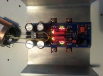
Anyway; holes for the IRFPs were drilled and threaded, 100uF caps and IRFPs soldered, power connected and the lovely DCB1 lit up like a christmas tree
I measure a difference 0.04V between pos and neg rail and there is an offset of 0.029V between the left channel and signal ground. After half an hour the temperature had reached approximately 35 degrees centigrade on center legs of the IRFPs. The 10 Ohm resistors were just a tad warmer.
Attachments
0.029V offset is 29mV which is not good. You are looking for 0.005V (5mV) or less in both channels output. Use the mV range of your meter also or another meter to make sure. If there is a coupling capacitor in the power amp's input no worries for now but get a better matched JFET pair for the left channel to drop the offset. All other things look good. Measure voltage drop across each 10 Ohm resistor also.
Had time for some soldering between work and supper to day. (As it is friday, today's menu was grilled and sautéed beef, mushrooms and onions, Hasselback spuds and home made red wine gravy).
Anyway; holes for the IRFPs were drilled and threaded, 100uF caps and IRFPs soldered, power connected and the lovely DCB1 lit up like a christmas tree
Hi there JCP, saw you picture, may I ask for your heatsink measures? I mean, the footprint of your DCB1.
I'm putting it together after some months it's been in a shoebox with other components (yes...
) while I was away; I had a plan to dissipate on the face down the MURs also, but now I'd like to order a new heatsink for when I'm back at home.The heatsink is a piece of aluminium U-bar, measuring about 20 cm wide. Length is just about equal to board lenght. The thickness of the base is 5 mm and the sides are 7 mm,- if my memory serves me right.
Resoldering didn't solve anything but looks. Is it the jfet quadruple by the output relay I need to look into? If yes,- how? I'm on thin ice here
Resoldering didn't solve anything but looks. Is it the jfet quadruple by the output relay I need to look into? If yes,- how? I'm on thin ice here
JCP,
twist the transformer wires.
Are they paired secondaries?
Then use two twisted pairs from transformer to PCB.
The input to the PCB is a 3terminal connection. Two of the secondaries fit into one terminal. Don't get them mixed up after twisting.
Hi Andrew, All,
I am finishing my DCB1 Hyopnotize as well. Was looking for an advice on how to wire the 2 pairs output transformer.
Say I am having this configuration
Should I wire 0s in CT or a consequent wire
1. Should this be non consequent
Terminal 1 (left) Red
Terminal 2 (Center) Black and Orange
Terminal 3 (Right) Yellow
2. Should this be consequent
Terminal 1 (left) Red
Terminal 2 (Center) Black and Yellow
Terminal 3 (Right) Orange
The DCB1 power input is a 3wire connection.
You need a 3wire twisted triplet as the power feed.
The three wires from a centre tapped transformer make the required twisted triplet.
A dual secondary has to be converted to a centre tapped by connecting two secondary wires together. TEST this with a bulb tester to ensure you have the correct AC voltages on the three wires.
I recommend that you do not rely on the manufacturer's colour coding. TEST it.
Last edited:
the DCB1 runs the regulator output at +-10Vdc.
You need at least 13-0-13Vac to get sufficient voltage drop across the CCS part of the Salas Shunt Regulators to get them to work as effective Constant Current Sources.
The next voltage available above 13-0-13Vac is 15-0-15Vac
Buy a new, correct transformer.
Transformers work with AC voltage.
You don't see + nor - voltages on the secondaries.
Use a Mains Bulb Tester, with a low wattage incandescent bulb.
It will protect your transformer from damage while you get the wiring right, or wrong.
Last edited:
Hi, just finished a new DCB1 (+LDR attenuator) preamp. The output of the power supply is good +/-9.88V and also the DC on the output is an acceptable 1-2mV.
The only problem is a 50Hz noise when the system is in MUTE. Did anybody face the same issue?
As soon as I completed the preamp I have had a 50Hz noise so strong that it was audible also when the preamp was off and the final amp (based on Hypex module) was on
The problem was related to the 220V chain connections: I removed all the faston, soldering all the connections from the 220V cord to the transformer. That reduced the noise reeeeeally a lot.
But I still have the 50Hz noise in MUTE.
Really appreciate an advice? anything I could investigate.
The metal case is not connected to the earth and, when in mute, the output is shortcutted to the 1MOhm resistor as in the original schema of the DCB1 buffer.
Transformer (toroidal) is in the same case, 25cm far from the audio section, no audible hum from it. Maybe I could try to add additional mechanical insulation such has 1mm of polystyrol under the trafo and also a thin layer of metal all around it.
The input is disconnected or connected to my macbook (no impact on the noise level).
The input is disconnected or connected to my macbook (no impact on the noise level).
Try a normal volume pot too so to check that its not the LDR that picks something and needs shielding, different grounding, whatever. The dcb1 boards short their outputs to ground when the power is off. The very old ones were cutting off in series. You got an old single sided board? Short the output to ground when off to see if the hum goes. Then you can modify it if that is the case. Ground the case to dcb1 0 line is another test.
- Home
- Source & Line
- Analog Line Level
- Salas hotrodded blue DCB1 build