Thanks Andrew, I have that section under control. Now if you could take the time to describe how to take the signal from the pcb to the attenuator that has a R and L input, a R and L output, and a R and L ground tab. Sorry to require this much very basic help.
Here you go...
You have an Input, then WIPER is Output, and the GND is return in your terminology.
Attachments

yes, when the two sets of twisted pairs arrive at the 3pin INPUT of the DCB1 you have to connect the two Return Wires together to feed into the commoned Return pin.
This Return pin is probably labeled wrongly.
When will they ever learn?
The "ground" word causes confusion and not just among beginners.
Has no designation in our boards. Just has L -space- R with a common pad in-between.
Good, that makes them better than most.Has no designation in our boards. Just has L -space- R with a common pad in-between.
Here you go...
You have an Input, then WIPER is Output, and the GND is return in your terminology.
Thanks for trying to help. Awaiting Andrew's response for certainty in this matter.
Andrew,
So now that I understand the wiring form the Rca input to the pcbs let me take a crack at the next step, from the pcb to the attenuator.
Take an additional twisted pair one core from the R hot input pin, the other core from the center input pin and go to the attenuator, attaching the core from the R hot input to the R input of the attenuator the other core to the "GND" tab on the attenuator. Repeat for the L channel. This will result in two wires now connected to the R pcb input pin, four wires attached to the center pcb input pin and another two wires attached to the L pcb input pin. Yes?
Now, to get back to the Pcb, take a twisted pair one core from, the R attenuator output the other core from the R attenuator "GND" tab and attach the R output to the pcb input hot pin the other to the pcb input center pin. Repeat for the L channel Yes?
Stereo Volume Controls
This article might help. The diagram under (Lets Build One) shows the return wires in black, make your connections the same at the pot but please do as AndrewT suggests and twist these return wires together with their associated feed wires to reject interferance.
Substitute the RCA sockets on the right hand side of the diagram for the input pins on the DCB1. The two black return wires join together at and are connected to the centre pin of the three. The signal feed wire for each channel is then connected to it's corresponding pin, Left or Right.
If you find that you have max volume when the pot is turned fully counterclockwise, swap the connections to the outer pins (on the pot) around.
Horrible diagram.
As is usual it shows a generalised "ground" symbol !
Take TWO twisted wires from the Source to the vol pot.
Attach the Hot wire of the pair to the "top" of the vol pot.
Attach the Return wire of the pair to the "bottom" of the vol pot.
That completes this input circuit.
Well not quite.
Look at the ends of the twisted pair. Analyse what you see.
How big are the LOOPS at each end, where the twisted pair meets the other equipment?
Arrange the wiring so that the LOOP AREA is absolutely at a minimum at the send end AND at the receive end.
Now treat the vol pot as your source. take a twisted pair to the next piece in the system.
Attach the Hot wire of the pair to the wiper of the vol pot.
Attach the Return wire of the pair to the "bottom" of the vol pot.
Arrange the output wires to minimise the LOOP AREA at the vol pot.
Go to the other end. Attach the Hot wire of the pair to the receiver PCB Signal Input.
Attach the Return wire of the pair to the PCB Signal Return (often labeled GND, or ground, or -IN, or many others !). Again arrange the wires so that the LOOP AREA is minimised.
If you work with:
SOURCE
RECEIVER
Twisted Pair
and ONLY think about that for the connection you are trying to make, then it is VERY SIMPLE.
Just three items to think about, don't let anything else confuse, or contaminate your thinking, for THIS connection.
As a guide to quickly recognise the wires in a twisted pair, whether it's signal or power or speaker, try to use a consistent COLOUR for the RETURN wire.
I use black and green in my pairs. I know that green is always Return. I know that in a PAIR that Black is always Return.
But, I use triplets for much of my power and here my Black changes. That is a Big source for potential confusion, because here (in a power triplet) Black = -ve. Green = zero volts/Return. Red = +ve
It would be better if you did not copy my use of Black to mean two different wires.
Adopt a colour you have lots of.
BTW,
Yellow/Green is exclusively for the PERMANENT Safety Earth.
Last edited:
Horrible diagram.
As is usual it shows a generalised "ground" symbol !
A quick google found that, it shows the connections at the pot which is what he seemed to have a problem with and i did tell him to twist the returns around the feeds, didn't i.?
It does not show the connections at the pot.
It shows only two of the four connection required to wire up the vol pot correctly.
It shows the "bottom" of the vol pot connected to the generalised "ground".
That information is useless.
Look at the final picture after the heading "Let's Build One!"
That is NOT the way to wire up a vol pot.
It's this rubbish we find all over the internet and in books that misguides beginners and intermediates.
Complete Codswallop !
Last edited:
What total rubbish Andrew!
I and several million other people have wired pots using that exact connection layout and it works just fine. If you buy a commercial amp, chances are that is the way they connected the pot too.
Unless you shunt it, there is NO other correct way to do it. What to do with the returns is the point of discussion, not how to connect the thing up!
You could serve to confuse people even more with your answer, that connection layout is correct, it's your answer which is complete codswallop. Have a nice day!
Andrew, the past one or two posts are very interesting but also very confusing to me. Could you please take the time to continue your wiring lesson that we began and help me get from the pcb to the attenuators and back. You can see from the "quote" that I included I have taken a crack at this part of the wiring. I would greatly appreciate your continued correction of my mistakes and more "lessons" going forward.Andrew,
So now that I understand the wiring form the Rca input to the pcbs let me take a crack at the next step, from the pcb to the attenuator.
Take an additional twisted pair one core from the R hot input pin, the other core from the center input pin and go to the attenuator, attaching the core from the R hot input to the R input of the attenuator the other core to the "GND" tab on the attenuator. Repeat for the L channel. This will result in two wires now connected to the R pcb input pin, four wires attached to the center pcb input pin and another two wires attached to the L pcb input pin. Yes?
Now, to get back to the Pcb, take a twisted pair one core from, the R attenuator output the other core from the R attenuator "GND" tab and attach the R output to the pcb input hot pin the other to the pcb input center pin. Repeat for the L channel Yes?
That is NOT the way to wire up a vol pot.
It's this rubbish we find all over the internet and in books that misguides beginners and intermediates.
Is it just the semantics of the way the wires are drawn with MS paint (not being twisted), or is it the labeling of "ground"?
It is both: the way the wiring has big LOOP areas and that the "ground" has been taken way off to a remote location.Is it just the semantics of the way the wires are drawn with MS paint (not being twisted), or is it the labeling of "ground"?
There should not be a "ground" there at all. This is signal interconnecting.
We have a Source feeding the vol pot (Receiver). That is a two wire Flow and Return, that must be a close coupled pair. There is no "ground".
After the vol pot we have another Source to Receiver interconnect. This is again a two wire Flow and Return, that must be a close coupled pair. There is no "ground".
If the vol pot has some metal components that are not part of the audio signal path, (eg. control shaft and/or casing) then to minimise interference there can be some advantage in connecting these metal parts to the screening Chassis.
I posted thisAndrew, the past one or two posts are very interesting but also very confusing to me. Could you please take the time to continue your wiring lesson that we began and help me get from the pcb to the attenuators and back. You can see from the "quote" that I included I have taken a crack at this part of the wiring. I would greatly appreciate your continued correction of my mistakes and more "lessons" going forward.
Is there a part you don't understand?Take TWO twisted wires from the Source to the vol pot.
Attach the Hot wire of the pair to the "top" of the vol pot.
Attach the Return wire of the pair to the "bottom" of the vol pot.
That completes this input circuit.
Well not quite.
Look at the ends of the twisted pair. Analyse what you see.
How big are the LOOPS at each end, where the twisted pair meets the other equipment?
Arrange the wiring so that the LOOP AREA is absolutely at a minimum at the send end AND at the receive end.
Now treat the vol pot as your source. take a twisted pair to the next piece in the system.
Attach the Hot wire of the pair to the wiper of the vol pot.
Attach the Return wire of the pair to the "bottom" of the vol pot.
Arrange the output wires to minimise the LOOP AREA at the vol pot.
Go to the other end. Attach the Hot wire of the pair to the receiver PCB Signal Input.
Attach the Return wire of the pair to the PCB Signal Return (often labeled GND, or ground, or -IN, or many others !). Again arrange the wires so that the LOOP AREA is minimised.
If you work with:
SOURCE
RECEIVER
Twisted Pair
and ONLY think about that for the connection you are trying to make, then it is VERY SIMPLE.
Just three items to think about, don't let anything else confuse, or contaminate your thinking, for THIS connection.
Where is the signal coming from? That is the Source.
Where is the signal going to? That is the Receiver.
Each connection has a Source and a Receiver.
The wires are the connection.
Andrew,
I Understood your answer several posts ago. What I can't seem to get a straight, unambiguous answer to is in my specific case , where I have taken the RCA input to the PCB first, as per your instruction, what becomes the source going to the pot, the PCB input or another twisted pair from the RCA plug. This isn't this hard and I am not this dense.
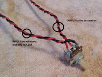
RCA input sockets connect directly to the pot - the picture DrDyna posted above shows the wires at the pot for one channel, duplicate this for the other.
The wires labeled output in that picture connect directly to the input tabs/pins on the DCB1 board.
You should have the following signal path. Input RCA's - Pot - DCB1 in - DCB1 out - Output RCA's
The output tabs/pins on the board connect directly to your output RCA sockets.
Twist the wires to help reject interferance.
- Home
- Source & Line
- Analog Line Level
- Salas hotrodded blue DCB1 build