Wow! Very nice build!!
Do
Hi Pinocchio,
Thanks for the comments. I have seen your build as well, very very nicely done! Congrats to you.
Since we are both from Montreal, maybe we should have a "DCB1s listening session" in a not so distant future...
I'd be very interested to listen to yours.
I am sure there's some kind of "DCB1 house sound"...
Anyway, merci et au plaisir, peut-être.
Regards
Scorpion
I'm matching the led-string for 9V. By using a bench power supply.
I've done a 2SK in series of the 5 leds (with the 2 pins shortened out).
when measuring the voltage over the led string. I see a lot of fluctuation when raising the power supply above 9 volts....a sort of steady state is reached @about 13 to 15V.
Then I can measure a voltage over the leds that is about 9,2Volts....and stops fluctuating a lot when I further incease the bench power supply.
So isn't it better to do a matching in circuit with the power supply of the B1? for doing it correctly? Because than I exactly know what value the voltage is? Or isn't this that important because the matching is done with the a same error?
Your idea is good.
The BEST way to measure a LED string (or any device requiring accuracy) is to implement the actual circuit working topology for the test.
A fixed voltage to replicate the PSU, with a jFET to replicate the circuit jFET and the LED string to replicate the 3, or 5, LEDs being used is perfect.
your voltages are WRONG.
The LEDs require ~5mA
The jFET requires > 2*Vp to act as a CCS.
What is the voltage across your single LED at 5mA?
What is the Idss of the LED?
How many LEDs are in the test string?
How many volts will be required for the whole string?
What is the Vp of the LED?
How many volts are needed to make it operate as a CCS?
I'm matching the led-string for 9V. By using a bench power supply.
I've done a 2SK in series of the 5 leds (with the 2 pins shortened out).
when measuring the voltage over the led string. I see a lot of fluctuation when raising the power supply above 9 volts....a sort of steady state is reached @about 13 to 15V.
Then I can measure a voltage over the leds that is about 9,2Volts....and stops fluctuating a lot when I further incease the bench power supply.
So isn't it better to do a matching in circuit with the power supply of the B1? for doing it correctly? Because than I exactly know what value the voltage is? Or isn't this that important because the matching is done with the a same error?
In circuit there will be only one Vbe voltage over the 5 Leds sum VF as extra. So measure the lot (K170+LEDS) with 10V DC PSU across.
In circuit there will be only one Vbe voltage over the 5 Leds sum VF as extra. So measure the lot (K170+LEDS) with 10V DC PSU across.
I don't understand it. When putting K170 and 5 leds in serie, feeding everything with 10 VDC and measering across...isn't that the same as measuring the power supply voltage of 10VDC?
Or do I have to put an extra resistor in series...which one will take a part of the power supply voltage?
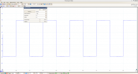
Did some measurements the other day.
To be honest I am a bit new fiddling with the scope. Anyway I feel my dcb1 is a bit to "light" in the bass Otherwise it sounds very good.
As volume control I use Lightspeed (ldr) - Maybe this is the sinner? I don't know yet.
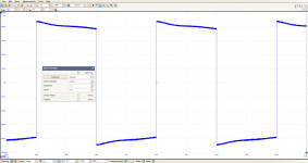
Perfect 1khz squarewave
Next to perfect 10khz squarewave
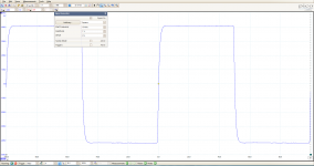
But what happens with the 50hz wave?
PS: This is running with no load.
To be honest I am a bit new fiddling with the scope. Anyway I feel my dcb1 is a bit to "light" in the bass Otherwise it sounds very good.
As volume control I use Lightspeed (ldr) - Maybe this is the sinner? I don't know yet.
Perfect 1khz squarewave
Next to perfect 10khz squarewave
But what happens with the 50hz wave?
PS: This is running with no load.
Attachments
Last edited:
DC couple the scope input for under 200ΗΖ squarewaves. They got a small value capacitor normally on AC input position.
The long run DCB1 subjective feedback merits the bass area so a feeling of lightness there its possibly due to a peripheral circuit or 600 Ohm input amplifier? On anything > 5kOhm it should do well.
Make sure that the input impedance of the LDR is easy on the source equipment used.
Also high hot-rod enhances the feeling of tonal completeness. Let it run in its electrolytics first before any further mod planning in any case.
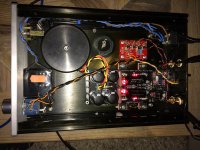
I did some drilling and rearranging, and put in all in the case, formerly known as a cd player:
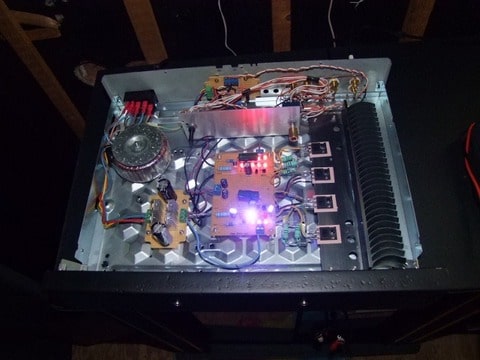
The blue leds are there by accident, standoffs were not high enough, so leds on the negative reg burned out.
Did some bypass cap testing also:
1. Teapo low ESR 470uF, this sounded better in the bass, a little faster. No measurable difference in noise
2. Tantalum 330uF shows that measuring is not all. Noise a little lower than above, but sounded metallic, so had to go
3. Russion PIO 0.22uF as bypass over the Teapo brought back the bigger stage, and slightly more transparent highs.
Happy now, so waiting for new red leds. When I need to remove the print for replacing these, the start delay and dc detecting system will be added.
Actually happy that it will take a while for the leds to arrive, time to listen!!
Thanks Salas!
Will post some daylight pics when fully finished. I am thinking about rebuilding the board so the leds will be arranged differently, allowing for shorter legs on the bypass caps. Before that I will build a breadboard LDR attenuator and see how that works, perhaps I will add that to the board also. Have found several different schematics for that, still trying to figure out which is the best. Pot is now Alps blue 50K, so a bit high...
Thanks for providing all the information and the schematics, I never thought the shunt supply would be such a big difference!!
Full DIY style. Congrats and enjoy.
Beautifull! Please keep on posting pictures....gives me ideas!!!
Salas,
On ebay the only stereo ones I see are the 09 types, are they recommended? Oh, and they only come in 50K
On hi-fi collective they sell the RV24 which looks more like a serious pot, but they do not come in 20 K, but in 10K and 100K. I guess the 10K is better for DCB1?
On ebay the only stereo ones I see are the 09 types, are they recommended? Oh, and they only come in 50K
On hi-fi collective they sell the RV24 which looks more like a serious pot, but they do not come in 20 K, but in 10K and 100K. I guess the 10K is better for DCB1?
Beautifull! Please keep on posting pictures....gives me ideas!!!
Thanks, will make some pics of the still unfinished case by daylight and post them here.
Basically I took a Sony CD player that was beyond fixing, took all innards out, and threw the front panel away. Out of a piece of wood ( oak in this case, it was a leftover piece just large enough ) I made a new front panel and sprayed it matte black.
I am always amazed about the price of even simple cases. Most of them on ebay that are affordable are in odd sizes, too small for my liking. The better looking cases still need the drilling and don't have any lettering on them, so the result when you want to do it all yourself will never be anywhere near professional finish. Then there are some cases that come predrilled with source selector and volume control position, and lettered accordingly, but they have the brand printed on the front panel. As it will be my amp, not the case builders, will not buy them too.
For me it is better to have a clearly diy built case, then the missing printing on the front looks more logical. When any of you have found a good way to get white letters on a black front in a neat way, please provide the info about how to do that. Black on aluminium is far easier, but I don't like aluminium fronts, they don't look good in my house.
My power amp is in a case ( and uses the transformer ) of a 2x150W PA amplifier. Still need to repaint the front panel ( it is aluminium ) but perhaps I will get my hands on a piece of sheet metal or aluminium and replace it completely. It has two pots for master volume setting that I don't need...
Sorry for the ramble
Salas,
On ebay the only stereo ones I see are the 09 types, are they recommended? Oh, and they only come in 50K
On hi-fi collective they sell the RV24 which looks more like a serious pot, but they do not come in 20 K, but in 10K and 100K. I guess the 10K is better for DCB1?
This one? 1pc Cosmos Tocos Potentiometer RV24YG 24mm A 10K? X2 Log Japan | eBay
If your sources drive 10K with ease its good.
This one? 1pc Cosmos Tocos Potentiometer RV24YG 24mm A 10K? X2 Log Japan | eBay
If your sources drive 10K with ease its good.
There is something strange going on. As I live in the Netherlands, I use ebay.nl
Even pasting the same description as in the ebay.com does not give any results!
But eh, yes that is certainly half the price as in hi-fi collective.
Question: how can I tell if my source is able to drive this pot? The only thing I know is that there is a Wolfson WM8501 in the Squeezebox Receiver with 1,7Vrms output.
Just try?
- Home
- Source & Line
- Analog Line Level
- Salas hotrodded blue DCB1 build