
Yes, just measure that your DAC has no DC offset problem for instance. See if the Quad uses an input coupling capacitor also. If there is even one in the whole system chain all prior DC probability stops at that point. Then then the amp's clamp just guards internal failure. The resistor approach will be a good idea only for the secondary output i.e. for some subwoofer drive, no need to add it on the main output too.I'll certainly pop some pictures up when I can work out how to do it. I have a funky heatsink arrangement that's worth a look if nothing else!
I don't quite get it, I should make sure there's no DC offset on the RCA outputs of my DAC? I'm guessing that whatever that reveals I need to make sure the power amp has an 'Output Voltage Offset clamp' (as it seems to be described in Quad circles) - it's some sort of speaker protection.
Regarding the DC coupling, would the resistor approach be better than two straight parallel connections to the DCB1 out?
Thanks again.
hello
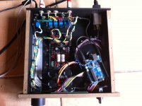
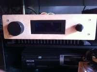
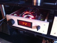
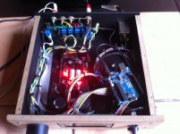
i enjoy my dcb1 with my litlle ACA. big thanks to all and diyaudio
some pictures to my modest work .
Magnifique!
Tell us more about the rest of your system.
Magnifique!
Tell us more about the rest of your system.
Thanks
Yes , i use m'y system with Tv and music only on phono .
I made Tony gee lbs clone ,m'y tournable is a 1200sl mk2 with ortofon blue , so dcb1 , ACA, and a preamp phono grado ph1 clone . A day .. I want to make your simplistic phono pre .
Nice work bullmout! Hi Salas, I think the Quad does have input coupling capacitors so I should be ok. I'm a bit lost re the resistor approach though and I don't know what this means "others just use 100R in series with the secondary outputs". Where would I put the resistors? I'm guessing that I connect the DCB1 board OUTs to one set of RCA sockets and put a resistor from each signal out terminal on the RCA to the signal out of the secondary RCA signal terminal. Where would I ground each secondary RCA socket? Sorry if I'm being a bit dim.
The B1 and the DCB1 both have output resistors fitted as standard.
220r is normal. Some suggest trying 100r, but add caution to check for instability.
If you ADD an extra output, then consider either:
a.) tap into the output side of the existing resistor.
b.) add an extra output resistor that taps into the input end of the existing resistor.
The Barrel of an RCA is not ground. That is why is is isolated from Chassis.
It is the Return part of the route that flows out through the Hot Pin.
Use a Twisted Pair up to the RCA and use a Twisted Pair on the other side of the RCA.
Last edited:
Thanks for the explanation Andrew, it's not as simple as I thought so I'll leave that for another time. Hmm... I'd already wired up the three pin DCB1 out with two twisted pairs and the RCA is isolated so I don't know where I got that ground idea from. I'll keep it simple for now! much appreciated.
I am trying to optimize the output coupling cap on my phono.
When using a pot right before DCB1, the input impedance seen by the source is actually the pot right? so in my case 22K?
BTW since I am using an output cap on my DCB1, I guess it would be ok to get rid of the cap in my phono? It is opamp based, and I might expect some DC in it at around 1V max?
When using a pot right before DCB1, the input impedance seen by the source is actually the pot right? so in my case 22K?
BTW since I am using an output cap on my DCB1, I guess it would be ok to get rid of the cap in my phono? It is opamp based, and I might expect some DC in it at around 1V max?
Last edited:
Yes, input Z is the pot's one.
It depends. If the offset from a phono is high due to its output capacitor was there to block several Volt of DC bias then it would disrupt the operation point of DCB1. If it was there to block just few mV of thermal drift offset then it would not disrupt the DCB1. 1V would just throw off its symmetry near clip. In any case you should measure what happens after the final coupling capacitor when the two devices are chained before connecting any power stage. DC level cycling can pass like LF pumping for instance. By charging the coupling cap in certain time pattern.
It depends. If the offset from a phono is high due to its output capacitor was there to block several Volt of DC bias then it would disrupt the operation point of DCB1. If it was there to block just few mV of thermal drift offset then it would not disrupt the DCB1. 1V would just throw off its symmetry near clip. In any case you should measure what happens after the final coupling capacitor when the two devices are chained before connecting any power stage. DC level cycling can pass like LF pumping for instance. By charging the coupling cap in certain time pattern.
I need expert advice for attenuator value. I'll buy tkd 2p65cs but confused between 25K or 100K. Dcb1 will be happy with 25K but I want the attenuator oneday in the future to be applicable for tube pre/amp which mostly require 100K.
My question : is it good to add 33K resistor paralel with 100K attenuator to make 25K total impedance?
My question : is it good to add 33K resistor paralel with 100K attenuator to make 25K total impedance?
you don't need to add a parallel 33k.
The DCB1 acts as a buffer. The output impedance of the Buffer is not affected by the vol pot impedance.
If the capacitances between the vol pot and the Buffer are kept very low the performance of the Buffer is not affected by the vol pot impedance.
The source will see the vol pot input impedance as the load.
Don't believe the MHZ numbers bcs not sure about the JFET model quality for such things vs real measurements including real cables on alternative source resistors. But it can show the trend for now. So I run the simulator: Say using a 10K pot at half point i.e. 5K in series -3dB=4.9MHZ, 20K pot at half 2.4MHZ, 50K pot at half 880kHz, 100K pot at half 360kHZ.
Many tens of kHz in the worst case and into the MHz in the best case.
Real figures would be helpful to our many builders and me.
They/we/I can decide what bandwidth is suitable for their/our Preamps and Buffers.
I will set up some practical test at a point. I got a 12MHZ function generator so it will cover.
I did a check and it gives 4MHZ -3dB low pass from 50 Ohm signal source. That is through 1m coax input cable and zero attn on the pot. With the 20K pot at half point it drops to 2.1MHZ. If driving the input cable from 1K25 and zero attn on the pot it drops to 1MHZ. Obviously the cable capacitance is forming an RC filter with the inserted high Zo.
Do your results indicate a limit, set by signal bandwidth that passes through, for the vol pot impedance?
Could it be 20k, or 50k, or 100k?
BTW, I set my Power Amplifiers input filter to 0.68us. This gives a signal bandwidth of ~200kHz.
I then try to get any source to feed in with a bandwidth approximately 1 octave above this so that the roll -offs don't add up.
Effectively I aim for ~400kHz.
Any higher gives no audio benefit to any audio signal, since my speakers cannot detect any additional roll off after passing the Power Amplifiers input filter.
Last edited:
- Home
- Source & Line
- Analog Line Level
- Salas hotrodded blue DCB1 build