The 2SK170s have +/- 40VDS max spec in this circuit but there is their dissipation limit intervening. Its for VDS*IDSS on each. VDS=|PSU| here. Don't run more than 130mW on each audio signal FET if you want them to live super long. Certainly not more than 200mW. I don't recommend any other supply voltage than +/- 10V BTW. Its what I preferred subjectively during the DCB1 development and It can still pass ~20Vpk-pk AC signal on that PSU level.
Hi tea-Bag,
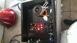
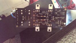
Thank you for replying. All the LEDs light when tested with the DMM.
I've checked each component and it's polarity when powered off. My soldering is a bit rough but all the pads look sound as far as I can see.
The next stage is to dive in with it turned on and take some measurements. This is my first project with mains voltage supply so I'm a bit nervous - hence why I'm testing it in the kitchen (where the nearest door is).
Where would you recommend going next?
Attachments
Last edited:
if you reduce the Vac input voltage, try a 6Vac+6Vac transformer, you can short the outputs to Power Ground/Zero Volts.
This tests the CCS part of the upper and lower circuits.
Once you know that the CCSs are working correctly. you can put back the full Vac and check the voltages around the Shunt stages.
The set of OUT LEDs is very telling.
This tests the CCS part of the upper and lower circuits.
Once you know that the CCSs are working correctly. you can put back the full Vac and check the voltages around the Shunt stages.
The set of OUT LEDs is very telling.
Completed DC-B1
Hi Guys
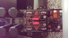
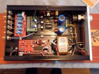
I completed my preamplifier based on the DC-B1 several months ago.
I would just like to thank Salas and others for there input and time. The project turned out great and I am very happy indeed with the sound.")
The preamp has full remote control with a "Lightspeed" attenuator controlling the volume.
Here are some pics-
Jeremy
Hi Guys
I completed my preamplifier based on the DC-B1 several months ago.
I would just like to thank Salas and others for there input and time. The project turned out great and I am very happy indeed with the sound.
The preamp has full remote control with a "Lightspeed" attenuator controlling the volume.
Here are some pics-
Jeremy
Attachments
Hi Salas
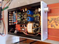
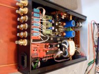
Thank you. The CCS are IRF610 and IRF9610 as used in your SSLV regs. I had them on hand and they seem to work well.
The coils are actually bifilar wound copper CCS resistors . They have very little inductance. I found that the sound is influenced a lot by the resistor in this position. After trying different types including Mills I settled on this DIY "copper" resistor. After break-in it seemed to be the most balanced sounding (to my ears).
Thank you. The CCS are IRF610 and IRF9610 as used in your SSLV regs. I had them on hand and they seem to work well.
The coils are actually bifilar wound copper CCS resistors
. They have very little inductance. I found that the sound is influenced a lot by the resistor in this position. After trying different types including Mills I settled on this DIY "copper" resistor. After break-in it seemed to be the most balanced sounding (to my ears).Hi Guys
I completed my preamplifier based on the DC-B1 several months ago.
I would just like to thank Salas and others for there input and time. The project turned out great and I am very happy indeed with the sound.
The preamp has full remote control with a "Lightspeed" attenuator controlling the volume.
Here are some pics-
Jeremy
Very inspiring, thanks!
Hi Salas
Thank you. The CCS are IRF610 and IRF9610 as used in your SSLV regs. I had them on hand and they seem to work well.
The coils are actually bifilar wound copper CCS resistors
A very nice DIY touch those handmade resistors then. Some DCB1 and SSLV picky on parts quality people insist on Caddock thick film MP series being very suitable there regarding off-the-shelf solutions. Did you use any of those in the tryouts? Also, what make/type are those shiny dark coloured film capacitors?
BTW, what gear make the rest of the system that your remote controlled DCB1 serves in?
Hello again!
I'm considering increasing the Hot rod level of my DCB1. I'd like to verify some things before I blow anything up.....
If a 3 ohm CCS resistor gives 500 mA, then a 1 ohm ought to give 1.5 A?
Then P = I^2 * R gives 2.25 watts, so a 7 - 10 watt resistor (Caddock MP930 with clip on heatsink) ought to be fine?
Check the VGS curve for 1.5A in the datasheet. Subtract VGS from the LEDS VF total. Divide the outcome in Volt by the resistor in Ohm. That is the current prediction.
When choosing nominal power for resistor and its three times the burning power expected then it can support the heat in the long term without stress.
When choosing nominal power for resistor and its three times the burning power expected then it can support the heat in the long term without stress.
A very nice DIY touch those handmade resistors then. Some DCB1 and SSLV picky on parts quality people insist on Caddock thick film MP series being very suitable there regarding off-the-shelf solutions. Did you use any of those in the tryouts? Also, what make/type are those shiny dark coloured film capacitors?
BTW, what gear make the rest of the system that your remote controlled DCB1 serves in?
I did try the Caddock as CCS. They sound very clear and precise. Quite analytical sounding though. For a warmer and airier sound the 'BI Technologies' thick films are worth a listen. The film caps are WIMA MP3-X2 0.22uF.
My power amplifiers are AMP2 Tripath kits from 41Hz. They are fed off big EI core transformers. Your excellent SSLV1.1 shunt regs provide the 5V and 10V Mosfet drive. Usually I listen to CD through a clocked Marantz CD17KI, but I have just purchased a used Gyrodec turntable which I am looking forward to hearing. So a new DIY phono amp might also be on the cards!
Jeremy
just add a second 3ohm resistor.Hello again!
I'm considering increasing the Hot rod level of my DCB1. I'd like to verify some things before I blow anything up.....
If a 3 ohm CCS resistor gives 500 mA, then a 1 ohm ought to give 1.5 A?
Then P = I^2 * R gives 2.25 watts, so a 7 - 10 watt resistor (Caddock MP930 with clip on heatsink) ought to be fine?
That will change the voltage and you can calculate the new CCS current. Check fully warmed up temperatures.
Listen with this doubled resistor.
If that seems like an improvement, then consider adding a third 3ohm resistor, repeat the checks.
- Home
- Source & Line
- Analog Line Level
- Salas hotrodded blue DCB1 build