Houston I got a problem
Was turning up my power qua a Vario Transformer. Looked good It was shunting allright and no dc at output. Suddenly I discovered the Voltage was to high. Might have confused some leads from the transformer. It is made a little different than normal this toroid. The supply had stopped shunting.
Now I ask wich components to check for damage ? All diodes is ok and all resistors.

Thanks! I have got some that are 2.5 mm. Will see if I can get the triplets to match tonight.
How close a voltage drop between the two triplets is acceptable?
You are looking to offset VGS differences so they should be unmatched triplets by as much as the VGS difference you measure between your negative and positive CCS MOSFETs. You shoot for same Vrset.
Is that singleton LED (bottom right in this photo) a power indicator?
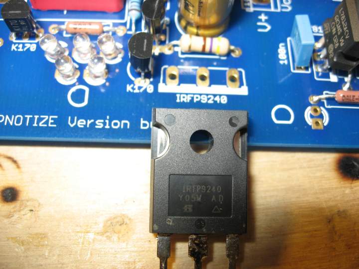
I see no picture but if you mean the one alone near a 2.2K resistor, yes its a point you can use for cabling to a front panel LED. Many just leave it there shining on the board, but it was meant as an indicator.
You are looking to offset VGS differences so they should be unmatched triplets by as much as the VGS difference you measure between your negative and positive CCS MOSFETs. You shoot for same Vrset.
Aha! Thanks. I have eight LEDS, with a Vf ranging from 1.590 V to 1.651 V there should be one or two in there that will do the job. ( Measured with a 1K3 resistor and 9 volt battery.)
I want to have the same value resistors setting the CCS.
I have no idea what you guys are talking about. I did the LED voltage test on reply 4 in this thread and matched up my LEDs nicely; I hope that's sufficient.
Hey, I know this is buried somewhere in this thread, but how should I wire up my Antek transformer (see image below) to the AC In (01 02 03) eyelets? Thanks!
Hey, I know this is buried somewhere in this thread, but how should I wire up my Antek transformer (see image below) to the AC In (01 02 03) eyelets? Thanks!
Attachments
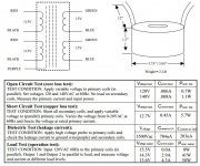
Are you sure you have the necessary skills to works with Mains Powered Projects?.................... how should I wire up my Antek transformer (see image below) to the AC In (01 02 03) eyelets? ..............
Hey, I know this is buried somewhere in this thread, but how should I wire up my Antek transformer (see image below) to the AC In (01 02 03) eyelets? Thanks!
The two secondary wires that are close together in the picture go to the middle connector screw. The outer ones go to one side screw each. Ask Antek if you ain't sure which wire is which and on how to recognize/configure the primary wires for your country's mains voltage.
I've ordered my chassis and have settled on hot rodding to 200mA. Reading through this thread I should still just about be able to mount the MOSFETS to the chassis floor and save on buying (& shipping!) some hefty heatsinks - plus I'm not keen on the way some of them look.
Elsewhere in the forum people suggest mounting the MOSFETS to a copper bar and then mounting the bar to the chassis to give it just that little bit extra mass, and therefore cooling potential. It seems to make sense to me but no one seems to have reported back on any success or failure. Does anyone here have any comments on the validity of this idea? The bottom to my case is 3mm aluminium 300mmx 260mm.
Elsewhere in the forum people suggest mounting the MOSFETS to a copper bar and then mounting the bar to the chassis to give it just that little bit extra mass, and therefore cooling potential. It seems to make sense to me but no one seems to have reported back on any success or failure. Does anyone here have any comments on the validity of this idea? The bottom to my case is 3mm aluminium 300mmx 260mm.
Thanks for the quick reply Salas. I've got some silipads and some thermal goo.
Well in that case I'm going to hot rod some more. The limiting factor in this is cooling without heatsinks. I don't want any visible externally and I won't have the space internally as I plan to have an attenuator, selector, tranny and an ODAC board inside.
Without knowing the thermal resistance of the bottom of my chassis its difficult to workout. I suppose the best way is to experiment.
- Home
- Source & Line
- Analog Line Level
- Salas hotrodded blue DCB1 build