Thanks! Perforated aluminum, not steel. But I think I'll take your advice anyway.  But I may also bolt the heat sinks to the AL base plate for extra dissipation.
I just found a massive copper heat sink in an old PC; it's a real piece of work. If I cut it in half I could put one half on either side.
Do my resistor (3R5 / 12W) , amperage (600 MA) and transformer (15+15, 50VA) specs sound right? Anything else I would need to upgrade or supersize?
But I may also bolt the heat sinks to the AL base plate for extra dissipation.I just found a massive copper heat sink in an old PC; it's a real piece of work. If I cut it in half I could put one half on either side.
Do my resistor (3R5 / 12W) , amperage (600 MA) and transformer (15+15, 50VA) specs sound right? Anything else I would need to upgrade or supersize?
Last edited:
DCB1, what 4 devices?Are there not 4 devices each passing 600 ma? 4x600ma = 2.4 A no?
Or are you talking about mA? is mA not equal ma?
A simulation with Duncan Amp tools says that R ought to be 10 ohms.
And ma does not equal mA
m = milli
A = Ampere.
mA = milli-Ampere.
ma does not mean anything.
What is the VA of the transformer.
The maximum continuous DC current from the PSU, when the transformer is feeding a capacitor input filter is ~VA/Vac(secondaries) / 2
For cool running divide by 2 again.
eg.
100VA 115:15+15Vac transformer results in 100/30/2=1.67Adc
I recommend ~50% for cool running and that comes out at recommended continuous cool running output = 0.83Adc.
Last edited:
Off topic but should any of you be interested. Lots of Black Gates/Mundorfs/Dynamicaps for sale:
http://www.diyaudio.com/forums/swap-meet/254027-black-gates-mundorf-dynamicap.html#post3878131
Thanks
Regards
Scorpion
http://www.diyaudio.com/forums/swap-meet/254027-black-gates-mundorf-dynamicap.html#post3878131
Thanks
Regards
Scorpion
Actually, ma does mean something. See 4-20ma sensors. I have not seen the unit mA in any of the controls/instrumentation literature which I have read.
Thank you for the example of how to use the formulas.
80 VA and 2x18 volt secondaries: 80/36/2 = 1.11 A x .50 = 550 mA.
80 VA and 2x15 volt secondaries: 80/30/2 = 1.33 A x .50 = 650 mA.
Is it correct that this max value refers to each rail and the current draw per rail is not to be summed in determining the capacity of the transformer?
Thanks.
Last edited:
Thanks! Perforated aluminum, not steel. But I think I'll take your advice anyway.
I just found a massive copper heat sink in an old PC; it's a real piece of work. If I cut it in half I could put one half on either side.
Do my resistor (3R5 / 12W) , amperage (600 MA) and transformer (15+15, 50VA) specs sound right? Anything else I would need to upgrade or supersize?
At around 600 MA, do I need to worry about heat sinks for the diodes along the back of the power supply caps, or is it OK just to screw them to the bottom plate?
Also, are the parts in Tea-Bag's kit (diodes and transistors) electrically insulated, such that I can mount more than one on a bare metal heat sink without any further insulation?
Thanks!
OK; thanks. I'll need to figure out a good way to insulate I guess. Hmmm.
Just ordered up a big-*** heat sink on eBay; I can cut it up or use it whole, bridging the underside of the board, if I flip the board over. Maybe I'll just cut it into fourths.
Oh, and one of the parts in the Tea-Bag kit came with a small bent-metal heat sink; I can't recall which part uses it. Should I upgrade that heat sink, too?
Last edited:
Ok, so the 10 Ohm 10 watt resistors are in place. This will allow for testing with the bigger EI transformer.
I cannot tell with certainty if the sound improved, but I think it did -- expectation bias or real, I cannot say.......However, it does seems more compelling / involving and quieter.
The voltage leaving the CRC is 17.11 and -17.16. The regulated is -10.3 and 10.26. S
I cannot tell with certainty if the sound improved, but I think it did -- expectation bias or real, I cannot say.......However, it does seems more compelling / involving and quieter.
The voltage leaving the CRC is 17.11 and -17.16. The regulated is -10.3 and 10.26. S
you'll need some tiny plastic washers, to isolate the screw holding down the transistor/diode made just for that purpose. I would use mica and thermal paste. Just the thinnest of coats of paste.
Thanks! The washers sound good. And actually, Tea-Bag supplied some nice thermal sheets of material that are supposed to go between the transistors and any heat sinks, rather than paste. But I may buy some paste to put between the heat sinks and the chassis.
Oh, and one of the parts in the Tea-Bag kit came with a small bent-metal heat sink; I can't recall which part uses it. Should I upgrade that heat sink, too?
If you mean the 7812's heatsink, it takes no upscale. That chip is an independent reg for the relay and its support circuitry. It does not change its dissipation regarding any main regs hot-rod.
It can't be Mega Amperes either.At around 600 MA, do I need to worry about heat sinks .............
They have been incorrectly marked.Actually, ma does mean something. See 4-20ma sensors. I have not seen the unit mA in any of the controls/instrumentation literature which I have read..
They have been incorrectly marked.
FYI: The Johnson Controls literature uses all three ma, mA and MA when describing the attributes of the same actuator.
You are right. They are using it incorrectly.
Last edited:
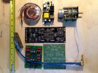
OK, here's my latest layout, while I wait for the 50VA transformer (and before I return the 30VA). You can see I have the Bent Audio remote control on a Goldpoint attenuator, and a 12 VDC power supply ($7 on eBay!) for the remote control motor.
Waiting on heat sinks.
Waiting on heat sinks.
Attachments
Does the quality of the resistor in the CRC power supply matter? I am currently using a plain old 10 W cement resistor. Would using something "better" be worthwhile?
I ask because differences have been noted in the regulator's current limiting input resistor.
Thanks for any observations!
Cheers!
I ask because differences have been noted in the regulator's current limiting input resistor.
Thanks for any observations!
Cheers!
- Home
- Source & Line
- Analog Line Level
- Salas hotrodded blue DCB1 build